ANTI-LOCK BRAKES
Anti-Lock Brakes Wiring Diagram (1 of 2) for Mercedes-Benz ML430 2001

List of elements for Anti-Lock Brakes Wiring Diagram (1 of 2) for Mercedes-Benz ML430 2001:
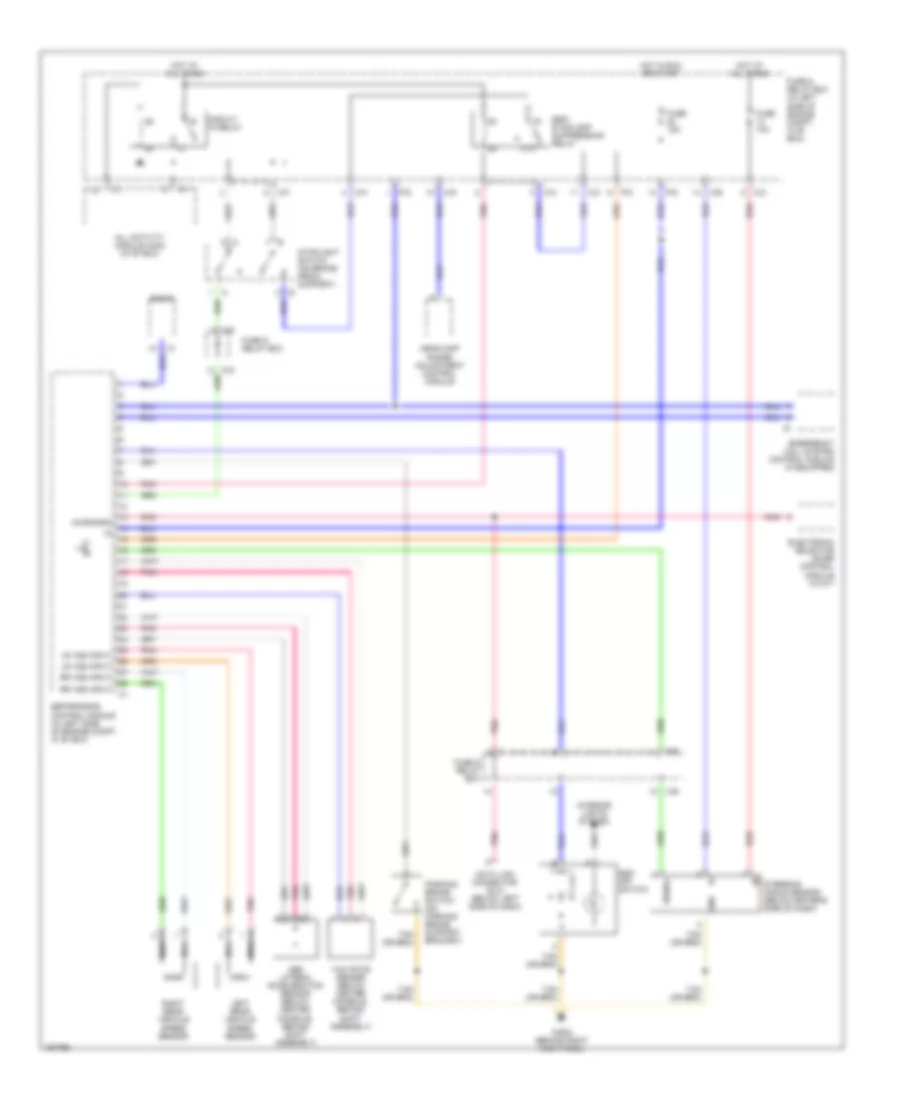
Anti-Lock Brakes Wiring Diagram (2 of 2) for Mercedes-Benz ML430 2001
List of elements for Anti-Lock Brakes Wiring Diagram (2 of 2) for Mercedes-Benz ML430 2001:
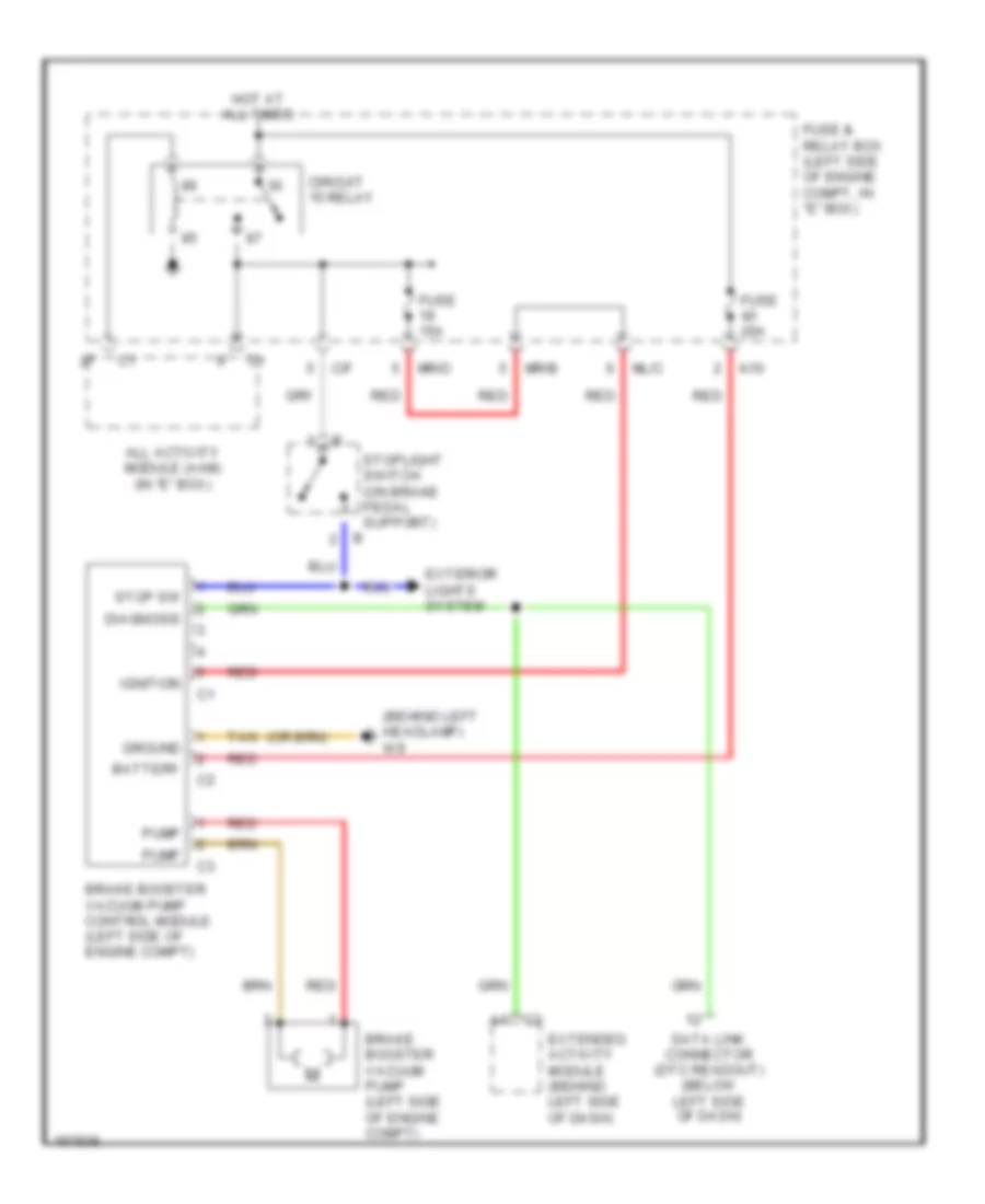
Brake Assist Wiring Diagram for Mercedes-Benz ML430 2001
List of elements for Brake Assist Wiring Diagram for Mercedes-Benz ML430 2001: