ANTI-LOCK BRAKES
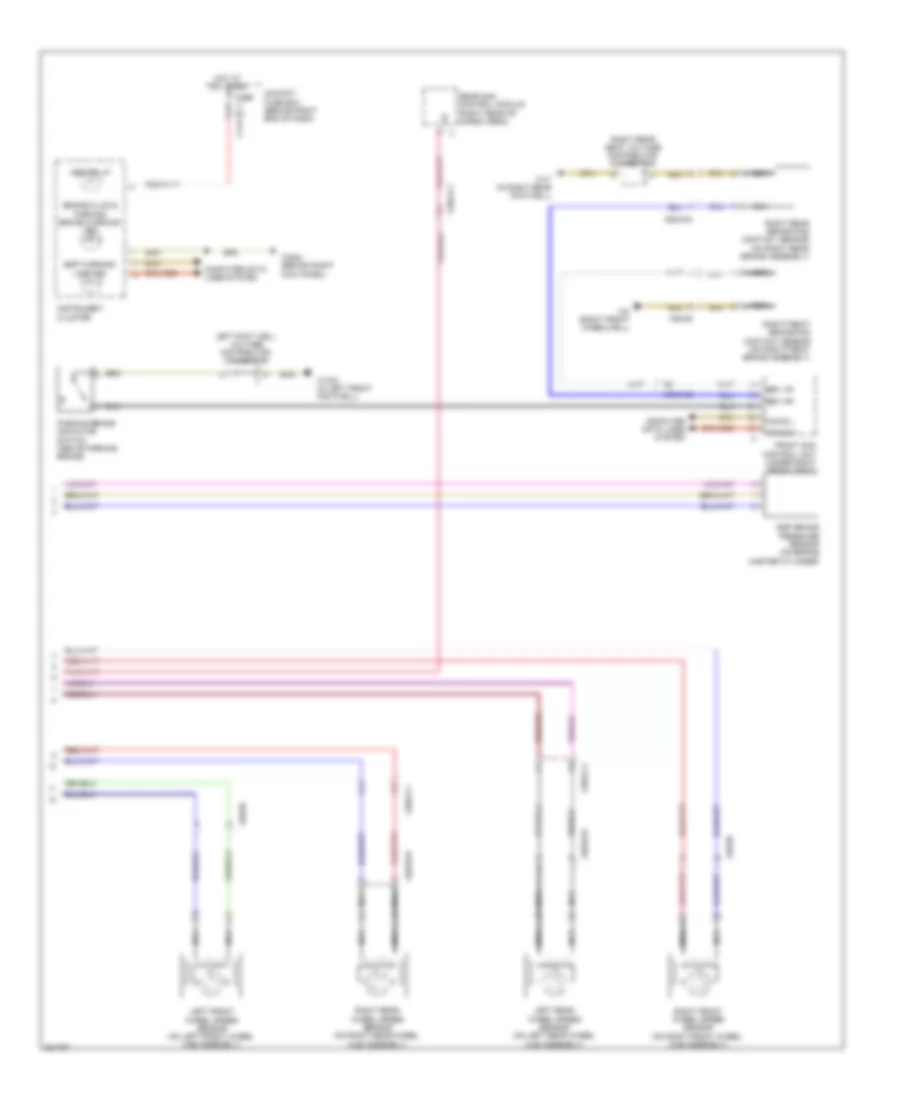
Anti-lock Brakes Wiring Diagram (1 of 2) for Mercedes-Benz R350 4Matic 2012

List of elements for Anti-lock Brakes Wiring Diagram (1 of 2) for Mercedes-Benz R350 4Matic 2012:
- (+)
- (-)
- (in left front wheelwell) w70
- (right front corner of engine compt) esp control module
- +5v
- Ba mv
- Bas brake booster
- Can-c h
- Can-c l
- Can-h h
- Can-h l
- Computer data lines system
- Dfhl_s
- Dfhr_s
- Dfvl_s
- Dfvr_s
- Diaphragm travel sensor
- Drs s
- Drs(-)
- Drs(5v)
- Engine compartment fuse & relay box (right side of engine compt)
- Front axle inlet solenoid valve
- Front axle switchover solenoid valve
- Front prefuse (right rear of engine compt)
- Fuse 100a
- Fuse 25a
- Fuse 5a
- High- pressure & return pump
- Hot at all times
- Hot in on or start
- Left front solenoid valve (pressure hold)
- Left front solenoid valve (pressure release)
- Left rear solenoid valve (pressure release)
- Ls1
- Ls2
- Lsa
- Micromechanical yaw rate sensor
- Mr3
- Mr4
- Pml
- Rear axle switchover solenoid valve
- Red
- Release switch
- Right front solenoid valve (pressure release)
- Right rear solenoid valve (pressure release)
- Sig
- Solenoid valve
- Solenoid valve rear axle inlet
- Sps (pml) solenoid valve (if equipped) (in left front wheelwell)
- Traction system hydraulic unit
- Valve (pressure hold) left rear solenoid
- Valve (pressure hold) right front solenoid
- Valve (pressure hold) right rear solenoid
- W/ ehps
- W70 (in left front wheelwell)
- X25/2-c1
Anti-lock Brakes Wiring Diagram (2 of 2) for Mercedes-Benz R350 4Matic 2012
List of elements for Anti-lock Brakes Wiring Diagram (2 of 2) for Mercedes-Benz R350 4Matic 2012:
- Abs ind lp
- Bbv hr
- Bbv vr
- Brake fluid & parking brake warning ind
- C11a
- Can b h
- Can b l
- Cockpit fuse box (behind right end of dash)
- Computer data lines system
- Esp brake pressure sensor (on brake master cylinder)
- Esp warning lamp ind
- Front sam control unit (under right front seat)
- Fuse 5a
- Hot at all times
- Instrument cluster
- Left foot well voltage distributor connector
- Left front wheel speed sensor (on left front wheel hub assembly)
- Left rear wheel speed sensor (on left rear wheel hub assembly)
- Nca
- Parking brake indicator switch (above parking brake)
- Rear sam control module (right rear of cargo area)
- Right front brake pad contact sensor (on right front brake assembly)
- Right front wheel speed sensor (on right front wheel hub assembly)
- Right rear brake pad contact sensor (on right rear brake assembly)
- Right rear seat voltage distributor connector
- Right rear wheel speed sensor (on right rear wheel hub assembly)
- W15/2 (in left front footwell)
- W17 (in right rear footwell)
- W2 (right front wheelwell)
- W29/2 (behind right kick panel)
- X25/2-c1
- X25/2-c2
- X62/32-d
- X62/33-d
- X62/33a
- X62/35
- X62/36