ANTI-LOCK BRAKES
Anti-lock Brakes Wiring Diagram (1 of 2) for Mercedes-Benz S500 2006

List of elements for Anti-lock Brakes Wiring Diagram (1 of 2) for Mercedes-Benz S500 2006:
- +12v
- +5v
- Asv 1
- Asv 2
- Ba mv+
- Ba mv-
- Brake booster (bas)
- Df vl
- Df vr
- Dg+5v
- Dg-sig
- Dgm
- Esp brake pressure sensor (behind left headlamp unit)
- Esp/sps/bas control module
- Front axle switchover
- Front axle vacuum
- Fuse 150a
- Fuse 50a
- High pressure/ return pump
- High pressure/ return pump relay
- Hl av
- Hl ev
- Hot at all times
- Hr av
- Hr ev
- Left front fuse/relay module (left rear of engine compt)
- Left front hold
- Left front release
- Left front wheel speed sensor (at left front wheel)
- Left rear hold
- Left rear release
- Ls1
- Ls2
- Lsr
- Mpm
- Mps
- Mra
- Mru
- Nca
- Pml+
- Pml-
- Rear axle switchover
- Rear axle vacuum
- Red
- Release switch
- Right front hold
- Right front release
- Right front wheel speed sensor (at right front wheel)
- Right rear hold
- Right rear release
- Solenoid valve
- Sps solenoid valve (on power steering pump)
- Terminal block & fuse box (circuit 30 & 61)
- Traction system hydraulic unit (left front of engine compt)
- Travel sensor
- Um rfp
- Usv 1
- Usv 2
- Vl av
- Vl ev
- Vr av
- Vr ev
- W9 (left side of engine compt)
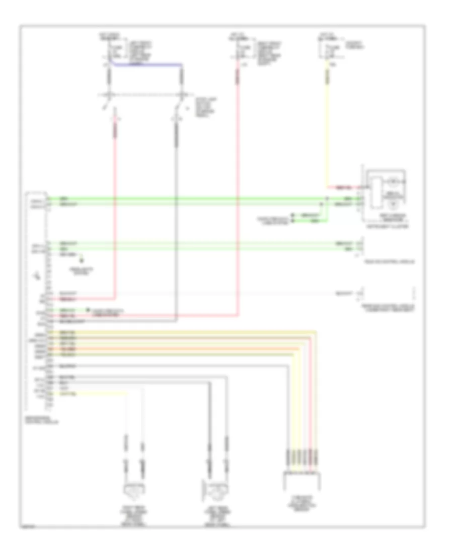
Anti-lock Brakes Wiring Diagram (2 of 2) for Mercedes-Benz S500 2006
List of elements for Anti-lock Brakes Wiring Diagram (2 of 2) for Mercedes-Benz S500 2006:
- +12v
- 79a
- Abs mil indicator
- Ay sig
- Bls
- Can-c h
- Can-c l
- Cockpit fuse box
- Computer data lines system
- Df hl
- Df hr
- Dfa vl
- Dfa vr
- Diag
- Drs+12v
- Drsm
- Drsr
- Drss
- Drst
- Esp warning indicator
- Esp/sps/bas control module
- Fuse 5a
- Fuse 7.5a
- Headlights system
- Hot at all times
- Hot in run or start
- Instrument cluster
- L15
- Left front fuse/relay module (left rear of engine compt)
- Left rear wheel speed sensor (at left rear wheel)
- Nca
- Rear sam control module (under right rear seat)
- Right front fuse/relay module (right rear of engine compt)
- Right rear wheel speed sensor (at right rear wheel)
- Stop lamp switch (on top of brake pedal)
- Tele aid control module
- Turn rate & lateral acceleration sensor