ANTI-LOCK BRAKES
Anti-lock Brakes Wiring Diagram (1 of 2) for Mercedes-Benz S550 2014

List of elements for Anti-lock Brakes Wiring Diagram (1 of 2) for Mercedes-Benz S550 2014:
- (left side of engine compt) w70
- 30g
- Ball valve front axle intake
- Ball valve rear axle intake
- Bls gnd
- Bls sup
- Brake vacuum sensor (on brake vacuum booster assembly)
- C213
- Can esp h
- Can esp l
- Clu gnd
- Clu sup
- Dzs hl h
- Dzs hl l
- Dzs hr h
- Dzs hr l
- Dzs vl h
- Dzs vl l
- Dzs vr l
- Electronic stability program control unit
- Engine fuse & relay module (right rear engine compt)
- Fr bm1
- Fr bp1
- Front pressure sensor
- Fuse 25a
- Fuse 40a
- Fuse 5a
- High pressure & return pump
- Hot at all times
- Hot w/ starter terminal 15 relay energized
- Instrument panel fuse box
- Left fuse & relay module (left end of dash)
- Mf2
- Pnk
- Rear pressure sensor
- Red
- Regulator valve (hold) left front pressure
- Regulator valve (hold) left rear pressure
- Regulator valve (hold) right front pressure
- Regulator valve (hold) right rear pressure
- Regulator valve (release) left front pressure
- Regulator valve (release) left rear pressure
- Regulator valve (release) right front pressure
- Regulator valve (release) right rear pressure
- Sig
- Stop lamp switch (top of brake pedal assembly)
- Switchover valve front axle
- Switchover valve rear axle
- Traction system hydraulic unit (left rear of engine compt)
- Ub (+)
- Vac gnd
- Vac sig1
- Vac sig2
- Vac sup
- Vehicle interior prefuse box (upper right footwell)
- W70 (left side of engine compt)
- X18/7-c1
- Yaw rate, lateral & longitudinal acceleration sensor (under left center of vehicle)
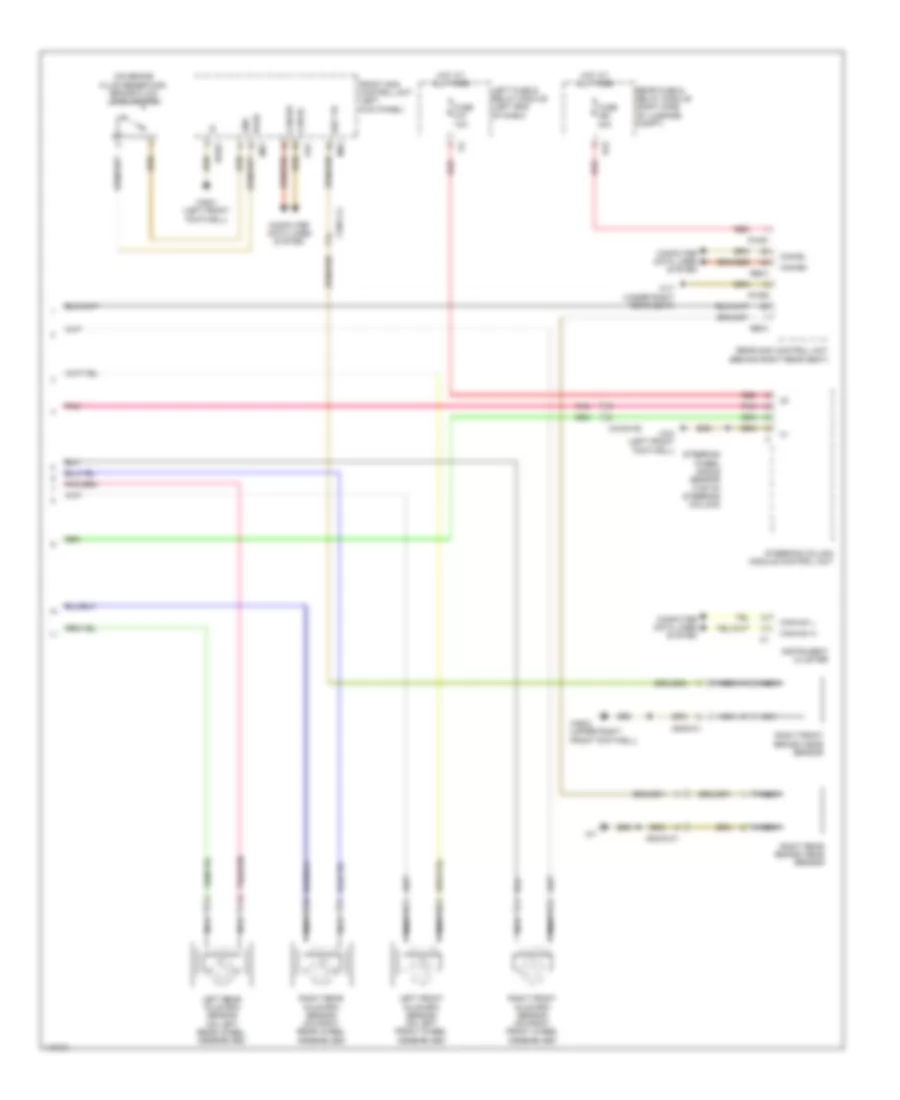
Anti-lock Brakes Wiring Diagram (2 of 2) for Mercedes-Benz S550 2014
List of elements for Anti-lock Brakes Wiring Diagram (2 of 2) for Mercedes-Benz S550 2014:
- (on brake fluid reservoir) brake fluid level switch
- Bbv vr
- Bfsd
- Can-bh
- Can-bl
- Can-hmi h
- Can-hmi l
- Coc
- Computer data lines system
- Front sam control unit (left kick panel)
- Fuse 10a
- Fuse 40a
- Gnd
- Hot at all times
- Instrument cluster
- Left front axle rpm sensor (on left front wheel assemblies)
- Left fuse & relay module (left end of dash)
- Left rear axle rpm sensor (on left rear wheel assemblies)
- Mr1
- Mr2
- Nca
- Pnk
- Pwr1
- Pwr2
- Rba1
- Rear fuse & relay module (right side of luggage compt)
- Rear sam control unit (behind right rear seat)
- Red
- Right front axle rpm sensor (on right front wheel assemblies)
- Right front brake wear sensor
- Right rear axle rpm sensor (on right rear wheel assemblies)
- Right rear brake wear sensor
- S15
- Steering column module control unit
- Steering wheel angle sensor (top of steering column)
- W17 (under right rear seat)
- W34 (left front footwell)
- W85/1 (left front footwell)
- W85/2 (upper right front footwell)
- X18/35-c2
- X18/7-c2
- X62/33-c1
- X62/6-c1