ANTI-LOCK BRAKES
Anti-lock Brakes Wiring Diagram (1 of 2) for Mercedes-Benz S550 4Matic 2010

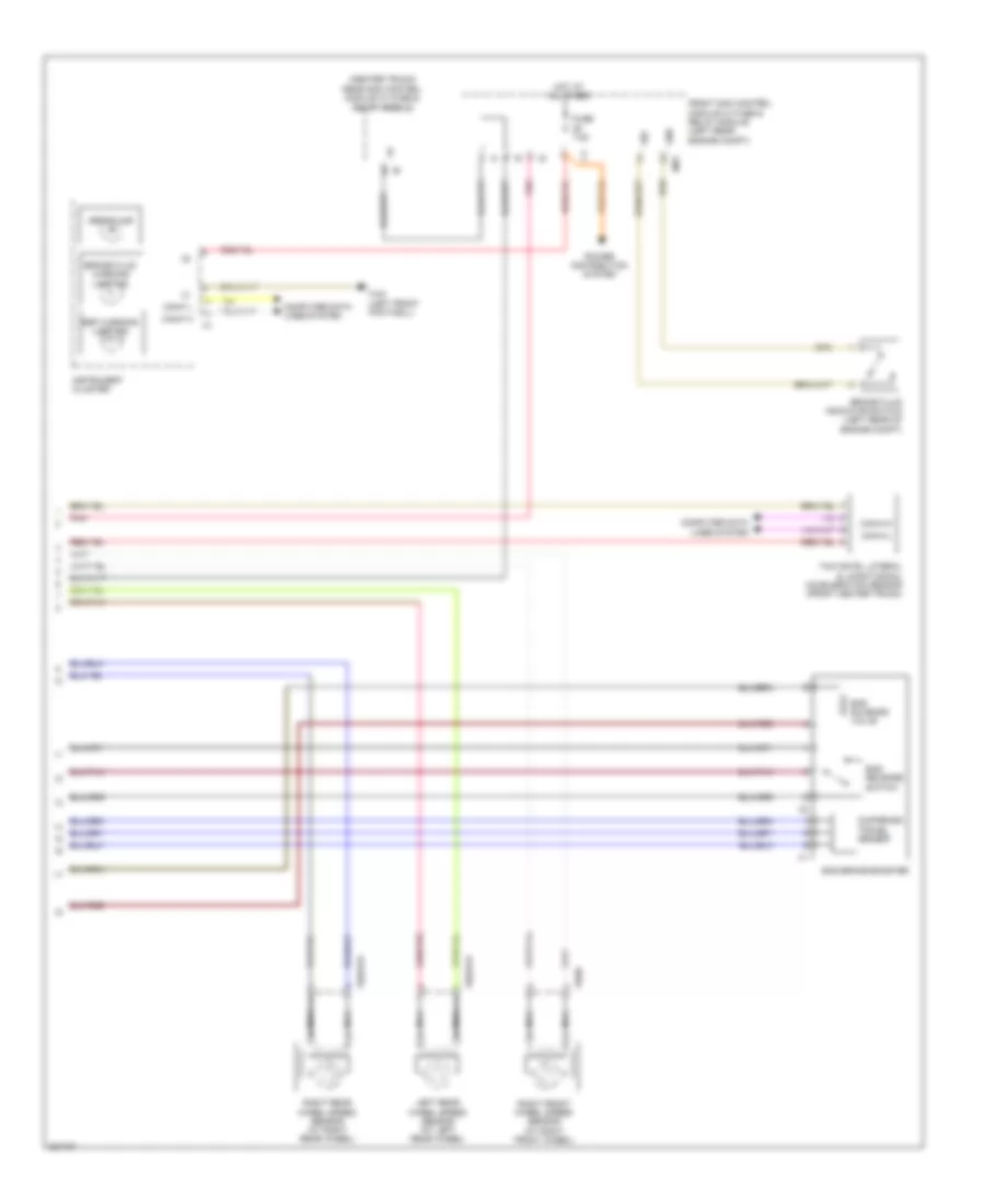
List of elements for Anti-lock Brakes Wiring Diagram (1 of 2) for Mercedes-Benz S550 4Matic 2010:
- (right front engine compt) esp control module
- 12v
- Attention assist sensor
- Bav a
- Bla
- Bls 12v
- Bls h
- Bls l
- Bls m
- Can e h
- Can e l
- Can h h
- Can h l
- Clu 12v
- Clu m
- Computer data lines system
- Df hl m
- Df hl s
- Df hr m
- Df hr s
- Engine compartment prefuse box (right rear engine compt)
- Front axle brake pressure sensor
- Front axle inlet solenoid valve
- Front axle switchover solenoid valve
- Fuse 25a
- Fuse 40a
- Fuse 7.5a
- High pressure & return pump
- Hot at all times
- Left front axle solenoid valve (hold)
- Left front axle solenoid valve (release)
- Left front pressure sensor
- Left front wheel speed sensor (at left front wheel)
- Left instrument panel fuse box (under left side dash cover)
- Left rear axle solenoid valve (hold)
- Left rear axle solenoid valve (release)
- Left rear pressure sensor
- Lrws 5v
- Lrws m
- Ls a
- Ls1
- Ls2
- Mp s
- Nca
- Pml 12v
- Pml a
- Pnk
- Rear axle inlet solenoid valve
- Rear axle switchover solenoid valve
- Red
- Right front axle solenoid valve (hold)
- Right front axle solenoid valve (release)
- Right front pressure sensor
- Right rear axle solenoid valve (hold)
- Right rear axle solenoid valve (release)
- Right rear pressure sensor
- Sps (pml) solenoid valve
- Stop lamp switch (top of brake pedal assembly)
- Traction system hydraulic unit
- Ub s
- W/ basic
- W/ premium
- W14/3 (right front engine compt)
- X18-c2
- X62/7
Anti-lock Brakes Wiring Diagram (2 of 2) for Mercedes-Benz S550 4Matic 2010
List of elements for Anti-lock Brakes Wiring Diagram (2 of 2) for Mercedes-Benz S550 4Matic 2010:
- (center trunk) rear sam control module w/ fuse & relay module
- Abs/mil ind
- Bas brake booster
- Bas release switch
- Bas solenoid valve
- Brake fluid indicator switch (left rear of engine compt)
- Brake fluid warning lamp ind
- Can-f h
- Can-f l
- Can-h-h
- Can-h-l
- Computer data lines system
- Diaphragm travel sensor
- Esp warning lamp ind
- Front sam control module w/ fuse & relay module (left rear engine compt)
- Fuse 7.5a
- Gnd
- Hot at all times
- Instrument cluster
- Left rear wheel speed sensor (at left rear wheel)
- Mr7
- Nca
- Pnk
- Power distribution system
- Right front wheel speed sensor (at right front wheel)
- Right rear wheel speed sensor (at right rear wheel)
- Sig
- W43 (left front footwell)
- X62/32-d
- X62/33-d
- X62/6
- Yaw rate, lateral & longitudinal acceleration sensor (front center trunk)