ANTI-LOCK BRAKES
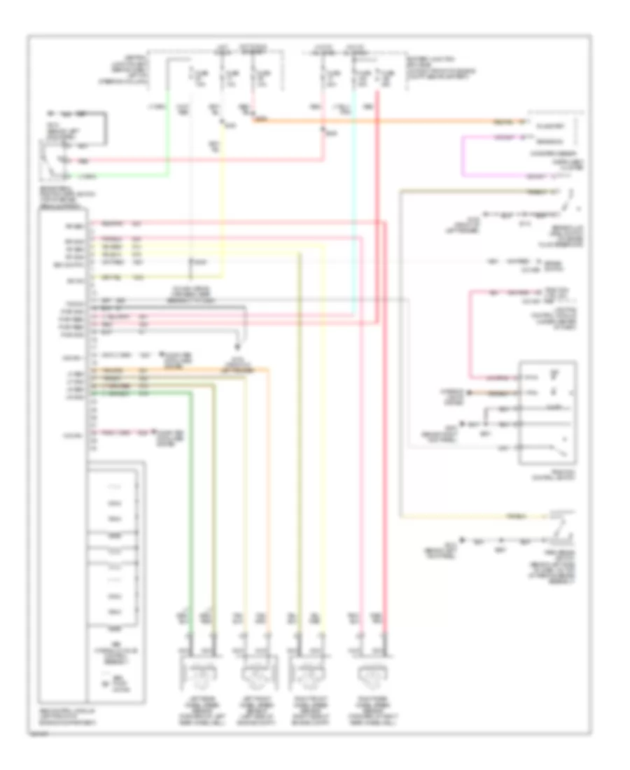
Anti-lock Brakes Wiring Diagram for Mercury Grand Marquis LS 2007
List of elements for Anti-lock Brakes Wiring Diagram for Mercury Grand Marquis LS 2007:
- (in main wiring harness, near breakout to c264)
- Abs control module (left front of engine compartment)
- Abs hydraulic valve control assembly
- Abs pump motor
- Battery junction box (bjb) (in right front of engine compt, behind battery)
- Boo switch
- Brake fluid level switch (on brake fluid reservoir)
- Brake ind
- Brake pedal position (bpp) switch (top of brake pedal support)
- Brake switch c2145b
- C2145a
- Central junction box (behind dash, left of steering column)
- Computer data lines system
- Ctrl sw ind
- Fuse 10a
- Fuse 20a
- Fuse 40a
- Fuse 7.5a
- G102 (front of left fender)
- G103 (front of left fender)
- G203 (behind right kick panel)
- G212 (behind left kick panel)
- Hot at all times
- Hot in run
- Hot in run or start
- Hs can +
- Hs can -
- Ign sw
- Illum
- Ind
- Instrument cluster
- Interior lights system
- Left front wheel speed sensor (left side of engine compt)
- Left rear wheel speed sensor (forward of left rear wheelwell)
- Lf gnd
- Lf sen
- Lighting control module (under center of dash)
- Lr gnd
- Lr sen
- Microprocessor
- Nca
- Park brake switch (behind left side of dash, on top of parking brake assembly)
- Pwr feed
- Pwr gnd
- Red
- Red/ pnk
- Red/pnk
- Rf gnd
- Rf sen
- Right front wheel speed sensor (right side of engine compt)
- Right rear wheel speed sensor (forward of right rear wheelwell)
- Rr gnd
- Rr sen
- Run/start
- S112
- S160
- S201
- S230
- S246
- S267
- S276
- Tcs sw
- Traction
- Traction control switch
 English