ANTI-LOCK BRAKES
Anti-lock Brake Wiring Diagrams for Mercury Mountaineer 2001
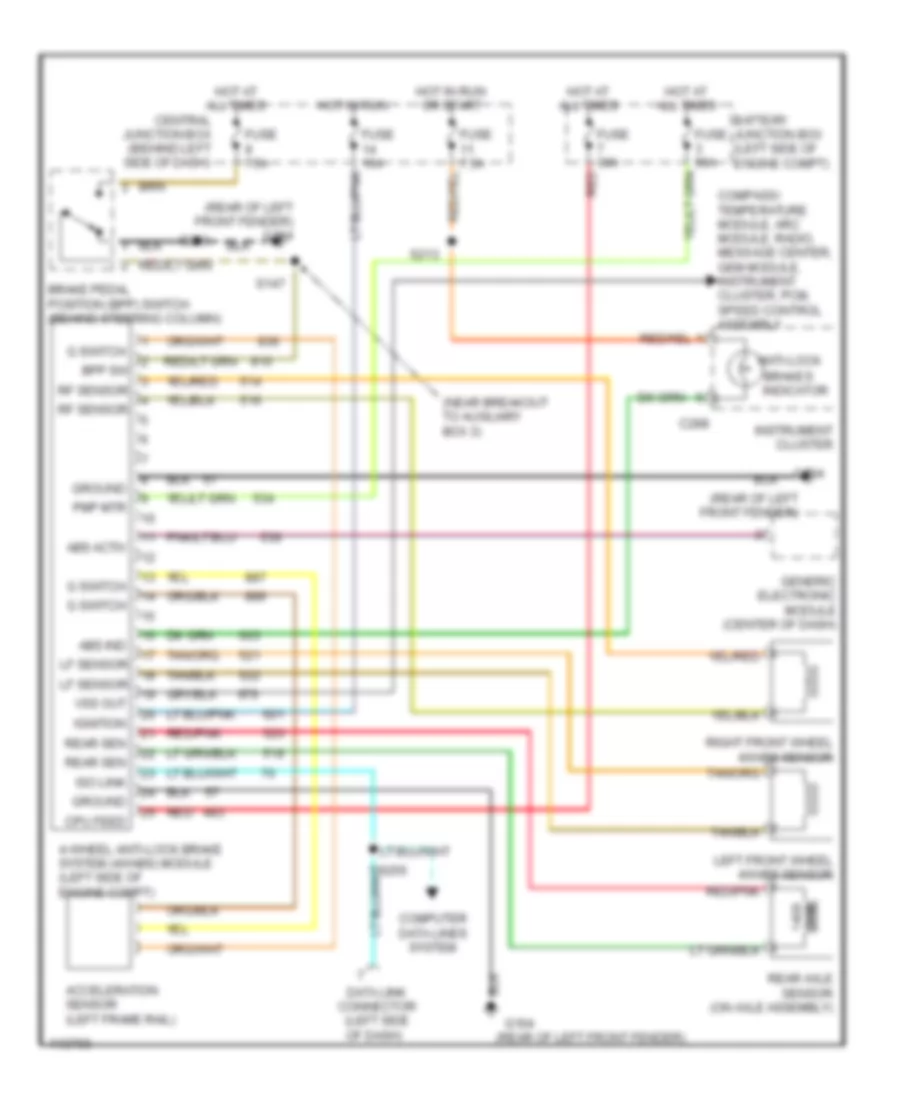
List of elements for Anti-lock Brake Wiring Diagrams for Mercury Mountaineer 2001:
- (near breakout to auxiliary box 3)
- (rear of left front fender)
- (rear of left front fender) g104
- 4-wheel anti-lock brake system (4wabs) module (left side of engine compt)
- Abs activ
- Abs ind
- Acceleration sensor (left frame rail)
- Anti-lock
- Battery junction box (left side of engine compt)
- Bpp sw
- Brake pedal position (bpp) switch (behind steering column)
- Brakes indicator
- C288
- Central junction box (behind left side of dash)
- Compass/ temperature module, arc module, radio, message center, gem module, instrument cluster, pcm, speed control assembly
- Computer data lines system
- Cpu feed
- Data link connector (left side of dash)
- Fuse 10a
- Fuse 30a
- Fuse 50a
- Fuse 7.5a
- G switch
- G104
- Generic electronic module (center of dash)
- Ground
- Hot at all times
- Hot in run
- Hot in run or start
- Ignition
- Instrument cluster
- Iso link
- Left front wheel 4wabs sensor
- Lf sensor
- Ohm
- Pmp mtr
- Rear axle sensor (on axle assembly)
- Rear sen
- Red
- Red/pnk
- Rf sensor
- Right front wheel 4wabs sensor
- S147
- S213
- S230
- Vss out
 English