ANTI-LOCK BRAKES
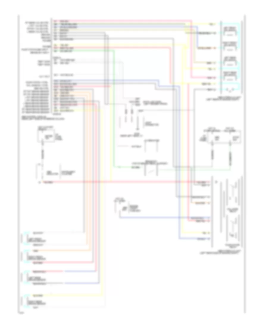
Anti-lock Brake Wiring Diagrams for Mercury Tracer 1994
List of elements for Anti-lock Brake Wiring Diagrams for Mercury Tracer 1994:
- (left fender apron)
- (left rear of engine compt)
- (left rear side of engine compt)
- (near left head lt)
- (near left side of steering column)
- (top of brake pedal support)
- 10a
- 15a
- 20a
- 60a
- A11
- Abs
- Abs control module
- Abs hydraulic unit
- Abs ind ctrl
- All times
- Alt volt
- Alternator
- B11
- B12
- B13
- B14
- B15
- B16
- B17
- B18
- Brake sensor
- Brake sw
- Brake sw input
- Cluster
- Compt
- Conn a
- Conn b
- Connector
- Data link conn
- Engine
- Fail safe
- Fail safe rly ctrl
- Fuse
- Fuse box
- G106
- Ground
- Hot at
- Hot in
- Hot in start
- I/p
- Indicator
- Instrument
- Joint
- L fnt brake sensor
- L fnt valve ctrl
- L rear brake sensor
- L rear valve ctrl
- Left front
- Left rear
- Meter
- Or run
- Panel
- Pnk
- Pnk 903
- Power
- Pump motor
- Pump mtr power input
- Pump mtr rly ctrl
- Relay
- Right front
- Right rear
- Rt fnt brake sensor
- Rt fnt valve ctrl
- Rt rear brake sensor
- Rt rear valve ctrl
- Solenoid
- Start or run
- Stop
- Test conn
 English