ANTI-LOCK BRAKES
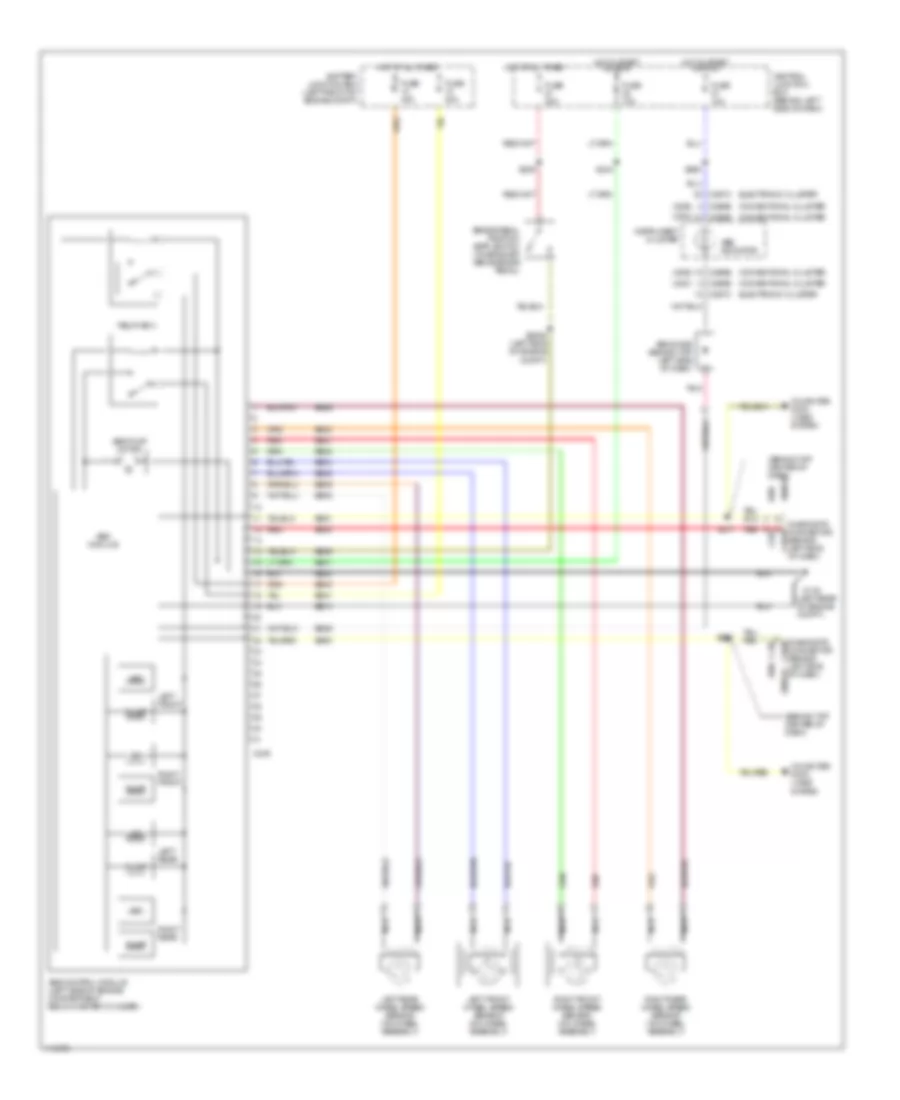
Anti-lock Brake Wiring Diagrams for Mercury Villager 1999
List of elements for Anti-lock Brake Wiring Diagrams for Mercury Villager 1999:
- (2000)
- (2001)
- (behind left side of dash)
- (behind top center of dash)
- (left rear of engine compt.)
- 2000-01
- Abs control module (left side of engine compartment below master cylinder)
- Abs diode (behind top left side of dash)
- Abs indicator
- Abs module
- Abs pump motor
- Battery junction box (left front of engine compt)
- Brake pedal position (bpp) switch (on bracket above brake pedal)
- Bs01
- Bs04
- Bs05
- Bs08
- Bs09
- Bs21
- Bs23
- Bs24
- Bs25
- Bs26
- Bs29
- Bs30
- Bs40
- Bs41
- Bs50
- Bs51
- C249
- C252
- C266b
- C267c
- Central junction box (behind left side of dash)
- Computer data lines system
- Connector (behind left side of dash)
- Conventional cluster
- Diagnostic c2018
- Diagnostic connector c2018
- Dump
- Eb10
- Eb20
- Electronic cluster
- Fuse 10a
- Fuse 20a
- Fuse 40a
- G116
- Hot at all times
- Hot in start or run
- Instrument cluster
- Iso
- Left front
- Left front wheel speed sensor (on wheel assembly)
- Left rear
- Left rear wheel speed sensor (on wheel assembly)
- Nca
- Pnk
- Red
- Relay box
- Right front
- Right front wheel speed sensor (on wheel assembly)
- Right rear
- Right rear wheel speed sensor (on wheel assembly)
- S2006 (left side of engine compt)
- S239
- S244
- S260
- S271
- S272
 English