ANTI-LOCK BRAKES
Anti-lock Brakes Wiring Diagram for MINI Cooper Works Clubman 2009
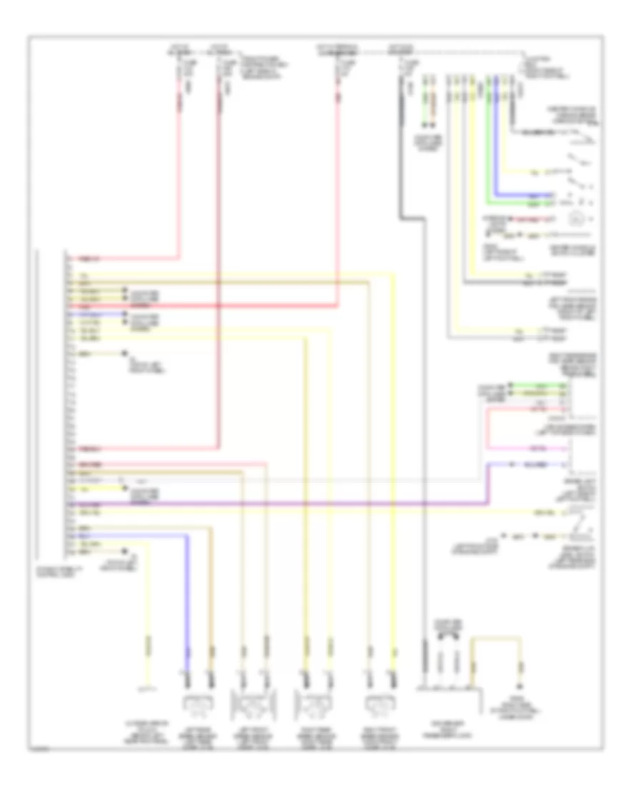
List of elements for Anti-lock Brakes Wiring Diagram for MINI Cooper Works Clubman 2009:
- (center console) parking brake warning switch
- Brake fluid level switch (left rear side of engine compt)
- Brake light switch (left side of left footwell)
- Car access system (left top side of dash)
- Center console switch cluster
- Computer data lines system
- Dsc sensor (right passenger floor)
- Dynamic stability control (dsc)
- Front power distribution box (left side of engine compt)
- Fuse f06 25a
- Fuse f18 5a
- Fuse f35 5a
- Fuse fl6 40a
- Hot at all times
- Hot in on or start
- Hot w/ terminal 30g energized
- Interior lights system
- Junction box (right side of right footwell)
- Left front brake pad wear sensor (front of left front wheel)
- Left front speed sensor (left front wheel hub)
- Left rear speed sensor (left rear wheel hub)
- Nca
- Outside mirror fold in (behind left rear trim panel)
- Red
- Right front speed sensor (right front wheel hub)
- Right rear brake pad wear sensor (behind right rear wheel)
- Right rear speed sensor (right rear wheel hub)
- X10318
- X11002
- X1108
- X14272
- X175 (left front side of engine compt)
- X2042 (left side of left footwell)
- X2846 (right side of right footwell, under door)
- X4 (top of left front wheel)
- X4010
- X4013
 English