ANTI-LOCK BRAKES
Anti-lock Brake Wiring Diagrams for Mitsubishi 3000GT Spyder VR-4 1995
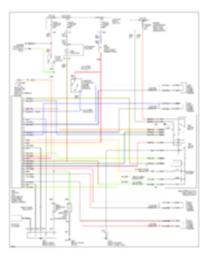
List of elements for Anti-lock Brake Wiring Diagrams for Mitsubishi 3000GT Spyder VR-4 1995:
- (awd)
- (hatchback only)
- A64
- A65
- Abs control
- Abs diode (right front fender panel)
- Abs hydraulic unit (right front of engine compt)
- Abs indicator
- Abs motor relay
- Abs resistor e-13
- Abs resistor f-45 (awd- convertible)
- Abs valve relay
- All times
- All-wheel drive (awd)
- All-wheel drive only
- C69
- C71
- C79
- C83
- Cd auto- changer
- Data link connector (partial) (right of steering column)
- Engine compartment relay box (right side engine compt)
- Front-wheel drive (fwd)
- Front-wheel drive only
- Fusible link 7 60a
- G sensor (w/ awd only) (under center console)
- G101 (front of right front wheel well)
- G307 (below right rear window)
- G407 (below trunk latch)
- Hot at
- Hot in on
- Hot in on or start
- Instrument cluster
- Junction block (left i/p)
- Left front wheel speed sensor
- Left rear wheel speed sensor
- Multi- pupose fuse 3 10a
- Multi- purpose fuse 11 15a
- Multi- purpose fuse 17 15a
- Nca
- Pnk
- Pump
- Red
- Right front wheel speed sensor
- Right rear wheel speed sensor
- Solenoid valves
- Stop light switch
- Twisted wire pair
- Unit (forward of right rear wheel well, below window)
- Unused connector
- W/ front-wheel drive only
 English