ANTI-LOCK BRAKES
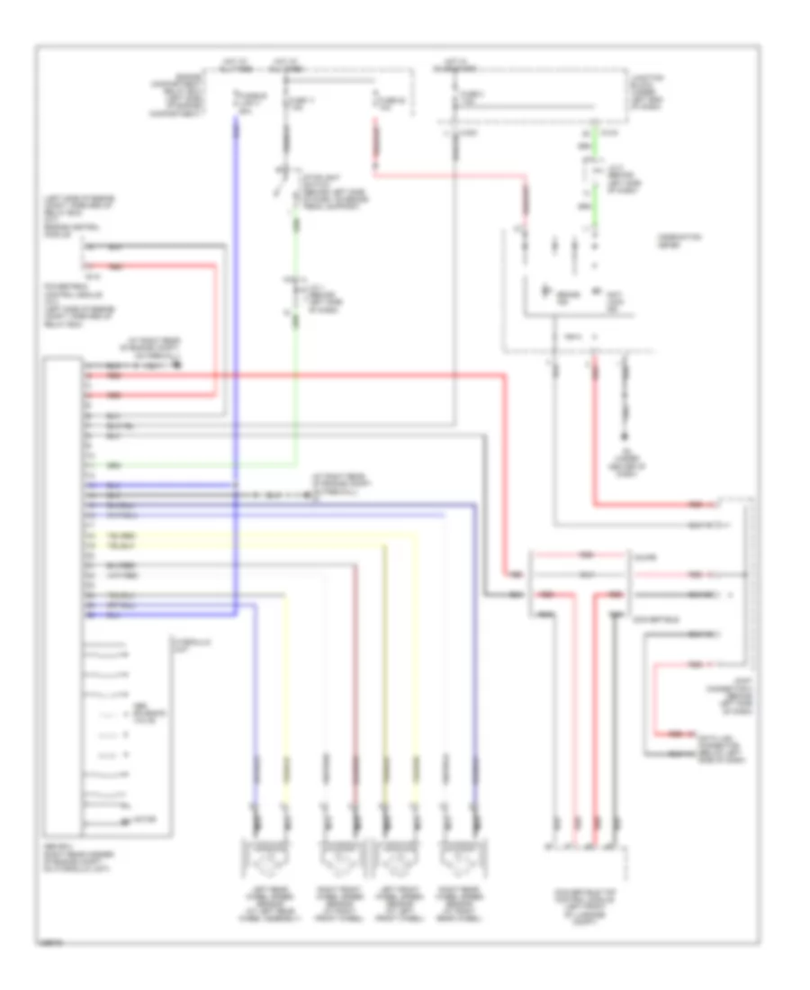
Anti-lock Brakes Wiring Diagram, with Traction Control for Mitsubishi Eclipse Spyder GS 2007

List of elements for Anti-lock Brakes Wiring Diagram, with Traction Control for Mitsubishi Eclipse Spyder GS 2007:
- (left side of engine compt, forward of relay box) (m/t) engine control module
- Abs solenoid valve
- Abs/tcl ecu (right rear corner of engine compt, on hydraulic unit)
- Anti lock ind
- B-18
- Brake ind
- C-203
- C-215
- Combination meter
- Convertible
- Convertible top control module (left front of luggage compt)
- Coupe
- D45
- Data link connector (below left
- Engine compartment relay box (left side of engine compartment)
- Fuse 11 7.5a
- Fuse 2 7.5a
- Fuse 20 7.5a
- Fuse 22 10a
- Fusible link 3 60a
- G1 (at right rear of engine compt, on firewall)
- G3 (under center of dash)
- Hot at all times
- Hot in on or start
- Hot w/ taillight relay energized
- Hydraulic unit
- Interior lights system
- J/c 1 (behind left side of dash)
- J/c 2 (behind left side of dash)
- Joint connector 3 (behind left side of dash)
- Junction block (under left end of dash)
- Left front wheel speed sensor (at left front wheel)
- Left rear wheel speed sensor (at left rear wheel assembly)
- Motor m
- Nca
- Powertrain control module (a/t) (left side of engine compt, forward of relay box)
- Red
- Right front wheel speed sensor (at right front wheel)
- Right rear wheel speed sensor (at right rear wheel)
- Side of dash)
- Stoplight switch (behind left side of dash, on brake pedal support)
- Tcl ind
- Tcl off ind
- Tcl switch
Anti-lock Brakes Wiring Diagram, without Traction Control for Mitsubishi Eclipse Spyder GS 2007
List of elements for Anti-lock Brakes Wiring Diagram, without Traction Control for Mitsubishi Eclipse Spyder GS 2007:
- (at right rear of engine compt, on firewall) g1
- (left side of engine compt, forward of relay box) (m/t) engine control module
- Abs ecu (right rear corner of engine compt, on hydraulic unit)
- Abs solenoid valve
- Anti lock ind
- B-18
- Brake ind
- C-203
- C-215
- Combination meter
- Convertible
- Convertible top control module (left front of luggage compt)
- Coupe
- Data link connector (below left
- Engine compartment relay box (left side of engine compartment)
- Fuse 11 7.5a
- Fuse 2 7.5a
- Fuse 22 10a
- Fusible link 3 60a
- G3 (under center of dash)
- Hot at all times
- Hot in on or start
- Hydraulic unit
- J/c 1 (behind left side of dash)
- J/c 2 (behind left side of dash)
- Joint connector 3 (behind left side of dash)
- Junction block (under left end of dash)
- Left front wheel speed sensor (at left front wheel)
- Left rear wheel speed sensor (at left rear wheel assembly)
- Motor m
- Nca
- Powertrain control module (a/t) (left side of engine compt, forward of relay box)
- Red
- Right front wheel speed sensor (at right front wheel)
- Right rear wheel speed sensor (at right rear wheel)
- Side of dash)
- Stoplight switch (behind left side of dash, on brake pedal support)