ANTI-LOCK BRAKES
Anti-lock Brakes Wiring Diagram for Mitsubishi Eclipse Spyder GT 2001
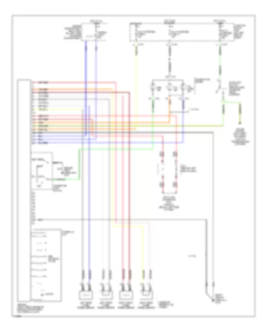
List of elements for Anti-lock Brakes Wiring Diagram for Mitsubishi Eclipse Spyder GT 2001:
- (inside of respective wheel)
- (right side of firewall) g123
- Abs ecu (right rear corner of engine compartment, on hydraulic unit)
- Abs ind
- Abs solenoid valve
- C-104
- C-107
- C-41
- C-42
- Combination meter
- Connector lock switch
- Cruise control, anti-theft, exterior lights & transmissions systems
- Data link connector (dlc) (partial) (below left side of dash)
- Engine compartment relay box (on left side of engine compartment)
- Fusible link 6 50a
- Hot at all times
- Hot in on
- Hot in on or start
- Hydraulic unit
- J/c 1 (behind left end of dash)
- Junction block (j/b) (on left end of dash)
- Left front wheel speed sensor
- Left rear wheel speed sensor
- Motor
- Multi- purpose fuse 3 15a
- Multi-purpose fuse 13 10a
- Multi-purpose fuse 9 10a
- Nca
- Off
- Right front wheel speed sensor
- Right rear wheel speed sensor
- Stoplight switch (behind dash, on brake pedal support)
- Tcl ind
- Tcl warn ind
- W/ tcl
 English