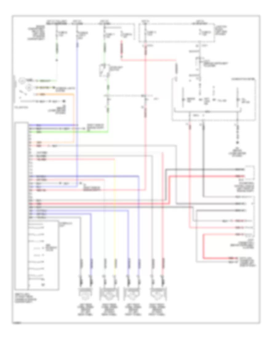
ANTI-LOCK BRAKES
Anti-Lock Brakes Wiring Diagram for Mitsubishi Endeavor Limited 2006

List of elements for Anti-Lock Brakes Wiring Diagram for Mitsubishi Endeavor Limited 2006:
Traction Control Wiring Diagram, with Active Skid Control for Mitsubishi Endeavor Limited 2006
List of elements for Traction Control Wiring Diagram, with Active Skid Control for Mitsubishi Endeavor Limited 2006:
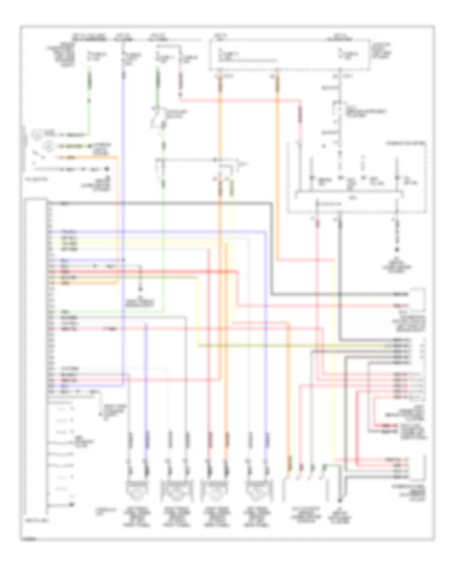
Traction Control Wiring Diagram, without Active Skid Control for Mitsubishi Endeavor Limited 2006
List of elements for Traction Control Wiring Diagram, without Active Skid Control for Mitsubishi Endeavor Limited 2006: