ANTI-LOCK BRAKES
Anti-lock Brake Wiring Diagrams for Mitsubishi Galant LS 1995
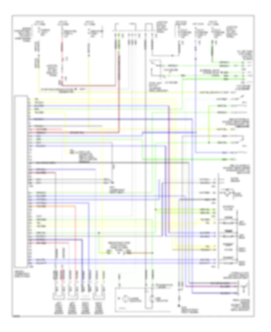
List of elements for Anti-lock Brake Wiring Diagrams for Mitsubishi Galant LS 1995:
- (at left side kick panel) junction block 2
- (behind right side of glove box, taped to harn) diode
- (red or)
- (w/ cruise)
- (w/o cruise)
- * w/o cruise ** w/ cruise
- 10**
- 17**
- 18*
- A42
- A43
- A44
- Abs ecu (under right side of dash)
- Abs indicator
- Abs motor relay (on right rear corner of engine compt, on abs motor)
- Abs valve relay (on right rear corner of engine compt, on abs motor)
- C35
- C37
- C41
- C45
- C46
- C49
- C53
- C54
- C64
- C65
- Charge indicator
- Combination meter
- Data link connector (below dash, left of center console)
- Dedicated fuse 1 30a
- Dedicated fuse 12 10a
- Engine compartment relay box (on right inner fender panel)
- Exhaust
- Exterior lights system (stop lamps)
- Fusible link 4 50a
- G105 (rear of right front fender)
- G301 (under right front seat)
- Hot at all times
- Hot in on
- Hot in on or start
- Hydraulic unit (on right rear of engine compartment)
- Intake
- Junction block 1 (at left side kick panel)
- Junction block 2 (at left side kick panel)
- Left front
- Left front wheel speed sensor
- Left rear
- Left rear wheel speed sensor
- Motor sensor
- Multi- purpose fuse 13 10a
- Multi- purpose fuse 5 15a
- Multi- purpose fuse 8 10a
- Nca
- Pedal stroke sensor (except 1996-98) (top of brake pedal bracket)
- Pump motor
- Red/
- Right front
- Right front wheel speed sensor
- Right rear
- Right rear wheel speed sensor
- Solenoid valves
- Starting/charging system (generator)
- Stop light switch (on brake pedal bracket)
 English