ANTI-LOCK BRAKES
2.0L
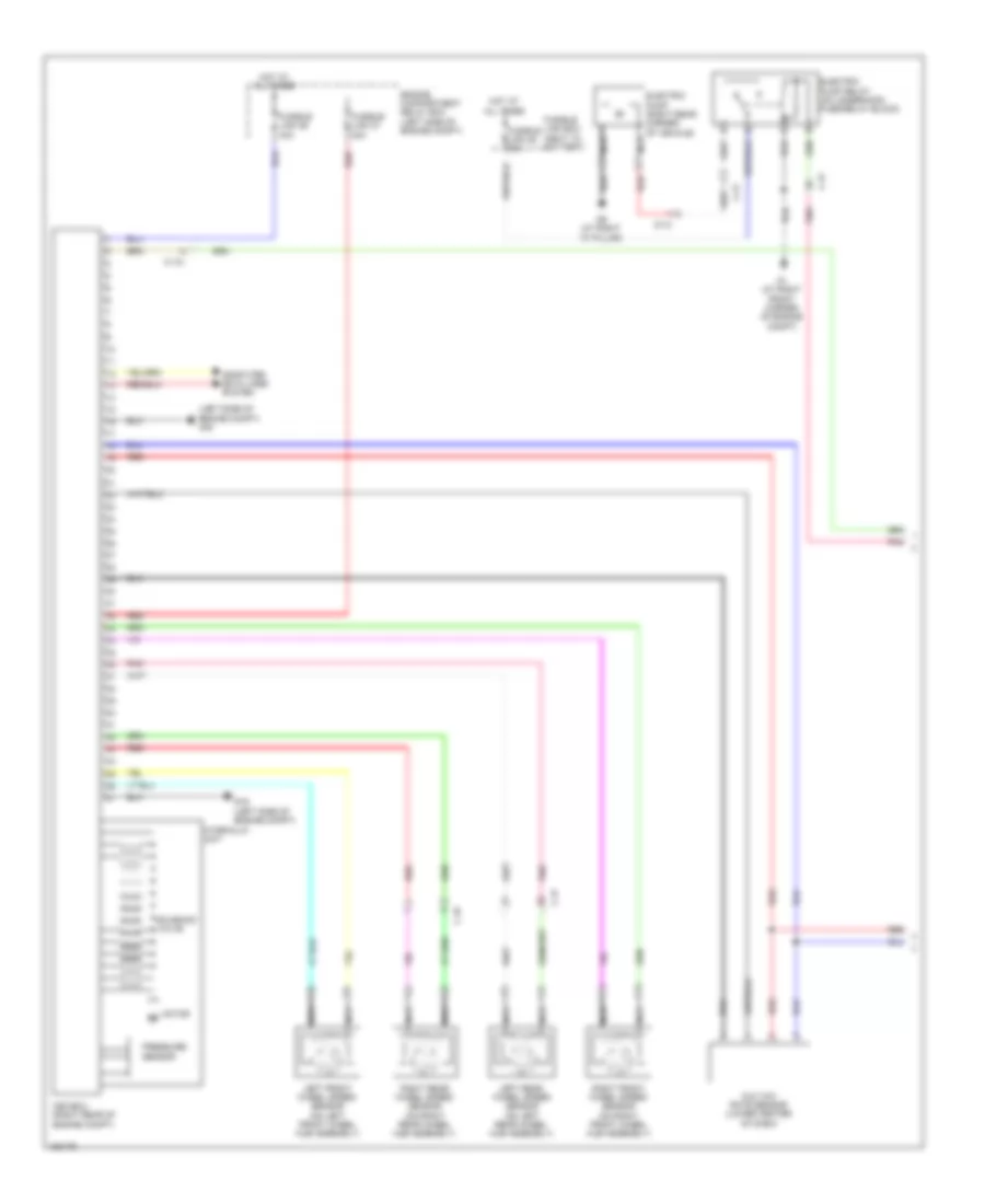
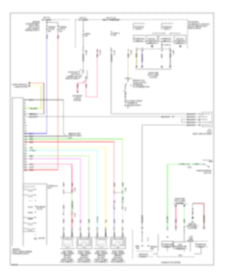
2.0L, Anti-lock Brakes Wiring Diagram, with Active Skid Control (1 of 2) for Mitsubishi Lancer ES Sportback 2014

List of elements for 2.0L, Anti-lock Brakes Wiring Diagram, with Active Skid Control (1 of 2) for Mitsubishi Lancer ES Sportback 2014:
- Asc-ecu (right rear of engine compt)
- C-39
- C-56
- Computer data lines system
- D-11
- D-15
- Engine compartment relay box (left side of engine compt)
- Fusible link 26 40a
- Fusible link 27 30a
- G & yaw rate sensor (lower center of dash)
- G13 (behind left side of dash)
- Hot at all times
- Hydraulic unit
- Left front wheel speed sensor (on left front wheel hub assembly)
- Left rear wheel speed sensor (on left rear wheel hub assembly)
- Motor m
- Nca
- Pnk
- Pressure sensor
- Red
- Right front wheel speed sensor (on right front wheel hub assembly)
- Right rear wheel speed sensor (on right rear wheel hub assembly)
- Solenoid valve
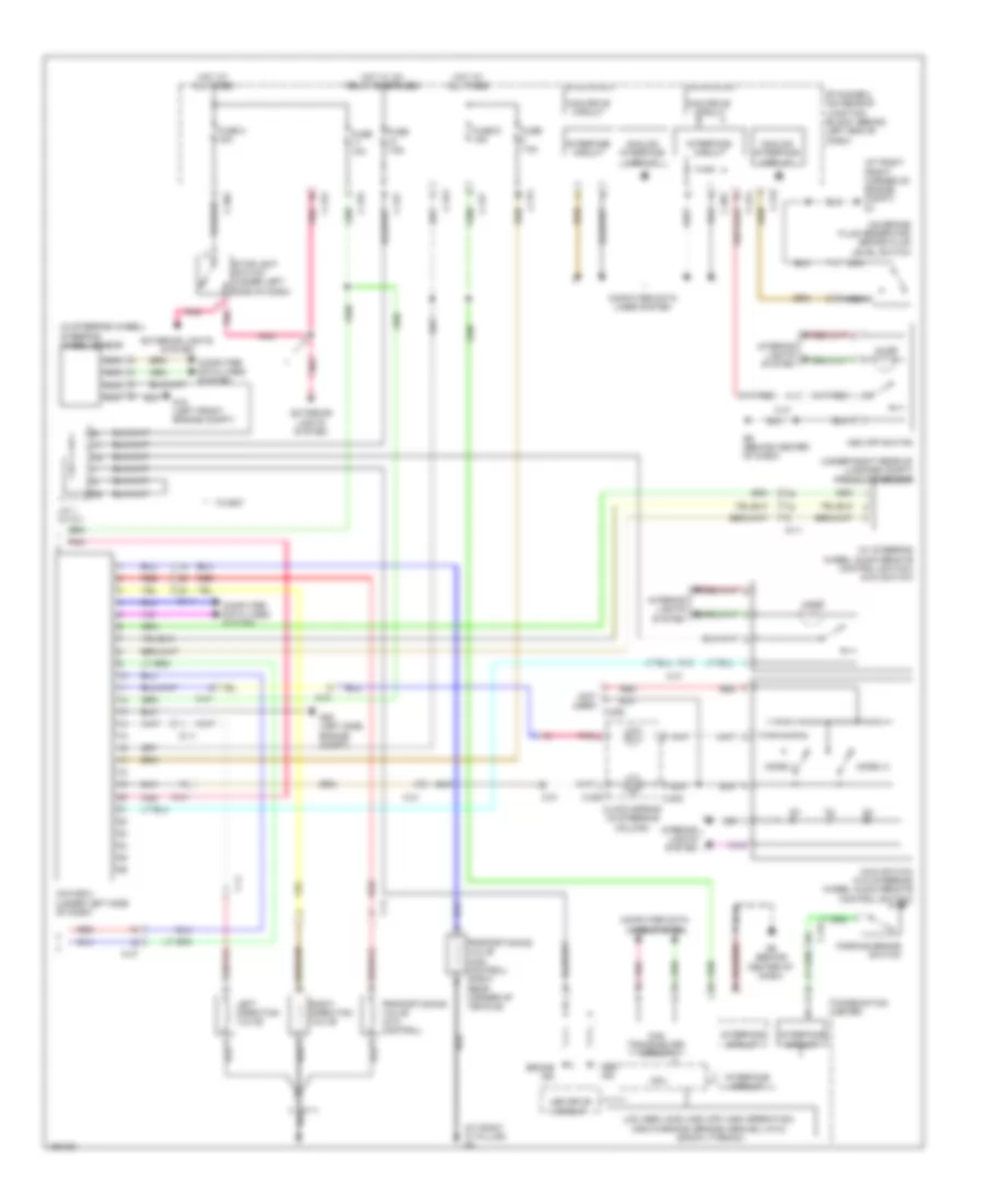
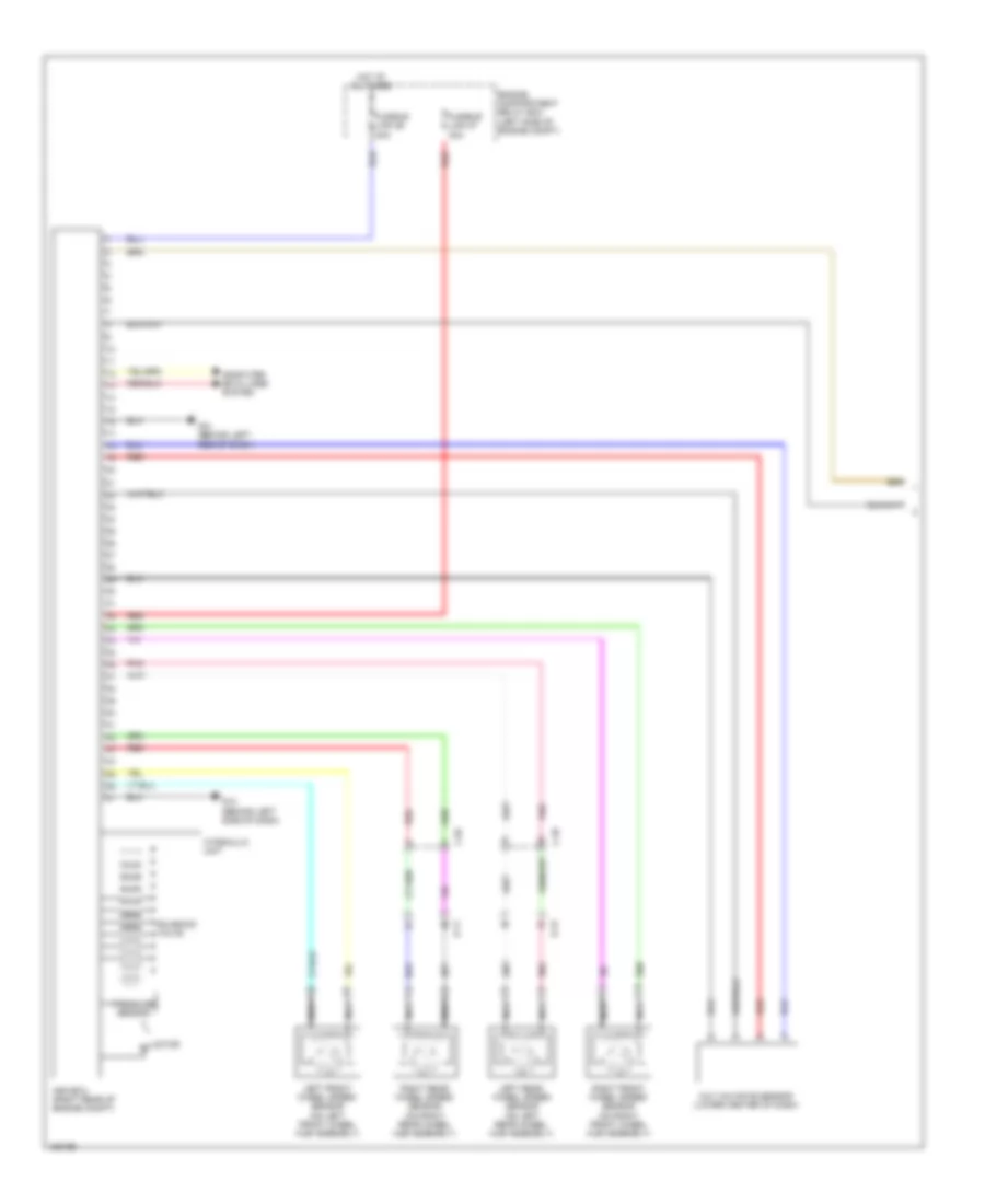
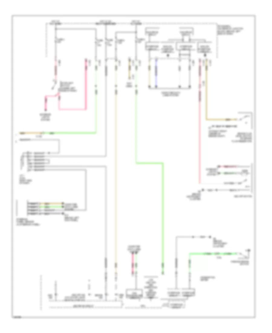
2.0L, Anti-lock Brakes Wiring Diagram, with Active Skid Control (2 of 2) for Mitsubishi Lancer ES Sportback 2014
List of elements for 2.0L, Anti-lock Brakes Wiring Diagram, with Active Skid Control (2 of 2) for Mitsubishi Lancer ES Sportback 2014:
- (at right front corner of engine compt)
- (not used)
- Abs ind
- Analog interface circuit
- Asc ind
- Asc off ind (w/o color liquid crystal display)
- Asc off switch
- Brake fluid level switch (on brake fluid reservoir)
- Brake ind
- C-128
- C-22
- C-301
- C-304
- C-311
- C-312
- C-313
- C-315
- C-317
- C-35
- C-51
- Can drive circuit
- Can transceiver circuit
- Combination meter
- Computer data lines system
- Cpu
- Etacs-ecu (on rear of junction block, behind left end of dash)
- Exterior lights system
- Fuse 10a
- Fuse 2 15a
- Fuse 7.5a
- Fuse 8 7.5a
- Fuse 9 15a
- G14 (behind left kick panel)
- G5 (behind instrument cluster)
- Hot at all times
- Hot w/ ig1 relay energized
- Illum
- Interface circuit
- Interior lights system
- J/c 1 (c-03) (right end of dash)
- Lcd (asc off) (asc operation) (asc warning) (brake) (abs)
- Led drive circuit
- Nca
- Parking brake switch
- Pnk
- Steering wheel sensor (in steering wheel)
- Stoplight switch (under left side of dash)
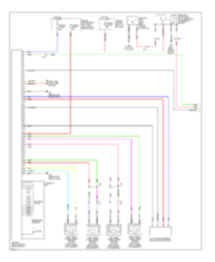
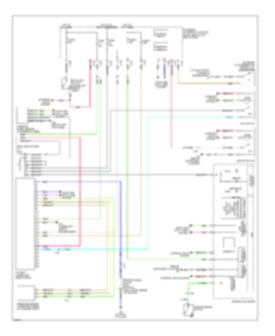
2.0L, Anti-lock Brakes Wiring Diagram, without Active Skid Control for Mitsubishi Lancer ES Sportback 2014
List of elements for 2.0L, Anti-lock Brakes Wiring Diagram, without Active Skid Control for Mitsubishi Lancer ES Sportback 2014:
- (at right front corner of engine compt) g1
- (behind left side of dash) g13
- Abs ind
- Abs-ecu (right rear corner of engine compt)
- Analog interface circuit
- Brake fluid level switch (on brake fluid reservoir)
- Brake ind
- C-22
- C-301
- C-304
- C-312
- C-317
- C-39
- C-56
- Can drive circuit
- Can transceiver circuit
- Combination meter
- Computer data lines system
- Cpu
- D-11
- D-15
- Engine compartment relay box (left side of engine compt)
- Etacs-ecu (on rear of junction block, behind left end of dash)
- Exterior lights system
- Fuse 12 7.5a
- Fuse 2 15a
- Fusible link 26 40a
- Fusible link 27 30a
- G5 (behind instrument cluster)
- Hot at all times
- Hot w/ ig1 relay energized
- Hydraulic unit
- Interface circuit
- J/c 1 (c-03) (right end of dash)
- Lcd (abs brake)
- Led drive circuit
- Left front wheel speed sensor (on left front wheel hub assembly)
- Left rear wheel speed sensor (on left rear wheel hub assembly)
- Motor
- Nca
- Parking brake switch
- Pnk
- Red
- Right front wheel speed sensor (on right front wheel hub assembly)
- Right rear wheel speed sensor (on right rear wheel hub assembly)
- Solenoid valve
- Stoplight switch (under left side of dash)
2.0L TURBO
2.0L Turbo, Anti-lock Brakes Wiring Diagram, Evolution (1 of 2) for Mitsubishi Lancer ES Sportback 2014
List of elements for 2.0L Turbo, Anti-lock Brakes Wiring Diagram, Evolution (1 of 2) for Mitsubishi Lancer ES Sportback 2014:
- (left side of engine compt) g19
- Asc-ecu (right rear of engine compt)
- C-131
- C-21
- C-45
- C-47
- Computer data lines system
- D-12
- Electric pump (right rear corner of vehicle)
- Electric pump relay (on underhood fuse/relay block)
- Engine compartment relay box (left side of engine compt)
- Fusible link 26 40a
- Fusible link 27 30a
- Fusible link 35 80a
- Fusible link box (next to battery)
- G & yaw rate sensor (lower center of dash)
- G1 (at right front corner of engine compt)
- G19 (left side of engine compt)
- G9 (at right "c" pillar)
- Hot at all times
- Hydraulic unit
- Left front wheel speed sensor (on left front wheel hub assembly)
- Left rear wheel speed sensor (on left rear wheel hub assembly)
- Motor m
- Nca
- Pnk
- Pressure sensor
- Red
- Right front wheel speed sensor (on right front wheel hub assembly)
- Right rear wheel speed sensor (on right rear wheel hub assembly)
- Solenoid valve
2.0L Turbo, Anti-lock Brakes Wiring Diagram, Evolution (2 of 2) for Mitsubishi Lancer ES Sportback 2014
List of elements for 2.0L Turbo, Anti-lock Brakes Wiring Diagram, Evolution (2 of 2) for Mitsubishi Lancer ES Sportback 2014:
- (at right "c" pillar) g9
- (at right front corner of engine compt) g1
- (in steering wheel) steering wheel sensor
- (not used) c-206
- (on brake fluid reservoir) brake fluid level switch
- (under right rear of luggage compt) pressure sensor
- (w/ steering wheel audio remote control switch) awc switch
- Abs ind
- Analog interface circuit
- Asc off switch
- Awc switch (w/o steering wheel audio remote control switch)
- Awc-ecu (under left side of dash)
- Brake ind
- C-202
- C-205
- C-23
- C-301
- C-304
- C-31
- C-311
- C-312
- C-313
- C-315
- C-317
- C-41
- C-47
- Can drive circuit
- Can transceiver circuit
- Clock spring (in steering column)
- Combination meter
- Computer data lines system
- Cpu
- D-11
- Etacs-ecu (on rear of junction block, behind left end of dash)
- Exterior lights system
- F-11
- Fuse 10a
- Fuse 2 15a
- Fuse 7.5a
- Fuse 9 15a
- G18 (left front engine compt)
- G20 (left side engine compt)
- G6 (behind center of dash)
- Hot at all times
- Hot w/ ig1 relay energized
- Ill
- Illum
- Interface circuit
- Interior lights system
- J/c 1 (c-101)
- Lcd (abs) (acd) (asc off) (asc operation) (asc warning) (brake) (gravel) (ayc) (snow) (tarmac)
- Led drive circuit
- Left direction valve
- Mode (+)
- Mode (-)
- Nca
- Parking brake switch
- Pnk
- Proportioning valve (acd control) (right rear corner of vehicle)
- Proportioning valve (ayc control)
- Red
- Right direction valve
- Stoplight switch (under left side of dash)
- Tc-sst
2.0L Turbo, Anti-lock Brakes Wiring Diagram, Except Evolution with Active Skid Control (1 of 2) for Mitsubishi Lancer ES Sportback 2014
List of elements for 2.0L Turbo, Anti-lock Brakes Wiring Diagram, Except Evolution with Active Skid Control (1 of 2) for Mitsubishi Lancer ES Sportback 2014:
- Asc-ecu (right rear of engine compt)
- C-128
- C-39
- C-46
- C-56
- Computer data lines system
- D-11
- D-15
- D-41
- Electric pump (right rear corner of vehicle)
- Electric pump relay (on underhood fuse/relay block)
- Engine compartment relay box (left side of engine compt)
- Fusible link 26 40a
- Fusible link 27 30a
- Fusible link 35 80a
- Fusible link box (next to battery)
- G & yaw rate sensor (lower center of dash)
- G13 (behind left side of dash)
- G18 (left front engine compt)
- G9 (at right "c" pillar)
- Hot at all times
- Hydraulic unit
- Left front wheel speed sensor (on left front wheel hub assembly)
- Left rear wheel speed sensor (on left rear wheel hub assembly)
- Motor m
- Nca
- Pnk
- Pressure sensor
- Red
- Right front wheel speed sensor (on right front wheel hub assembly)
- Right rear wheel speed sensor (on right rear wheel hub assembly)
- Solenoid valve
2.0L Turbo, Anti-lock Brakes Wiring Diagram, Except Evolution with Active Skid Control (2 of 2) for Mitsubishi Lancer ES Sportback 2014
List of elements for 2.0L Turbo, Anti-lock Brakes Wiring Diagram, Except Evolution with Active Skid Control (2 of 2) for Mitsubishi Lancer ES Sportback 2014:
- (abs)
- (acd)
- (asc off) (asc operation)
- (asc warning)
- (at right front corner of engine compt) g1
- (behind instrument cluster) g5
- (brake)
- (c-03)
- (gravel)
- (on brake fluid reservoir) brake fluid level switch
- (right end of dash) j/c 1
- (snow)
- (tarmac)
- Abs ind
- Asc ind
- Asc off switch
- Awc switch
- Awc-ecu (under left side of dash)
- Brake ind
- C-22
- C-301
- C-304
- C-311
- C-312
- C-313
- C-315
- C-317
- C-35
- Can drive circuit
- Circuit interface
- Circuit transceiver can
- Combination meter
- Computer data lines system
- Cpu
- D-11
- Etacs-ecu (on rear of junction block, behind left end of dash)
- Exterior lights system
- Fuse 10a
- Fuse 2 15a
- Fuse 7.5a
- Fuse 8 7.5a
- Fuse 9 15a
- G12 (under left side of driver's seat)
- G14 (behind left kick panel)
- G5 (behind instrument cluster)
- G9 (at right "c" pillar)
- Hot at all times
- Hot w/ ig1 relay energized
- Illum
- Interface circuit
- Interior lights system
- Lcd
- Led drive circuit
- Nca
- Parking brake switch
- Pnk
- Pressure sensor (under right rear of luggage compt)
- Proportioning valve (acd control) (right rear corner of vehicle)
- Rheostat
- Steering wheel sensor (in steering wheel)
- Stoplight switch (under left side of dash)
2.0L Turbo, Anti-lock Brakes Wiring Diagram, Except Evolution without Active Skid Control for Mitsubishi Lancer ES Sportback 2014
List of elements for 2.0L Turbo, Anti-lock Brakes Wiring Diagram, Except Evolution without Active Skid Control for Mitsubishi Lancer ES Sportback 2014:
- (at right front corner of engine compt) g1
- (behind left side of dash) g13
- Abs ind
- Abs-ecu (right rear corner of engine compt)
- Analog interface circuit
- Brake fluid level switch (on brake fluid reservoir)
- Brake ind
- C-22
- C-301
- C-304
- C-312
- C-317
- C-39
- C-56
- Can drive circuit
- Can transceiver circuit
- Combination meter
- Computer data lines system
- Cpu
- D-11
- D-15
- Engine compartment relay box (left side of engine compt)
- Etacs-ecu (on rear of junction block, behind left end of dash)
- Exterior lights system
- Fuse 12 7.5a
- Fuse 2 15a
- Fusible link 26 40a
- Fusible link 27 30a
- G5 (behind instrument cluster)
- Hot at all times
- Hot w/ ig1 relay energized
- Hydraulic unit
- Interface circuit
- J/c 1 (c-03) (right end of dash)
- Lcd (abs brake)
- Led drive circuit
- Left front wheel speed sensor (on left front wheel hub assembly)
- Left rear wheel speed sensor (on left rear wheel hub assembly)
- Motor
- Nca
- Parking brake switch
- Pnk
- Red
- Right front wheel speed sensor (on right front wheel hub assembly)
- Right rear wheel speed sensor (on right rear wheel hub assembly)
- Solenoid valve
- Stoplight switch (under left side of dash)
2.4L
2.4L, Anti-lock Brakes Wiring Diagram, with Active Skid Control (1 of 2) for Mitsubishi Lancer ES Sportback 2014
List of elements for 2.4L, Anti-lock Brakes Wiring Diagram, with Active Skid Control (1 of 2) for Mitsubishi Lancer ES Sportback 2014:
- Asc-ecu (right rear of engine compt)
- C-39
- C-56
- Computer data lines system
- D-11
- D-15
- Engine compartment relay box (left side of engine compt)
- Fusible link 26 40a
- Fusible link 27 30a
- G & yaw rate sensor (lower center of dash)
- G13 (behind left side of dash)
- Hot at all times
- Hydraulic unit
- Left front wheel speed sensor (on left front wheel hub assembly)
- Left rear wheel speed sensor (on left rear wheel hub assembly)
- Motor m
- Nca
- Pnk
- Pressure sensor
- Red
- Right front wheel speed sensor (on right front wheel hub assembly)
- Right rear wheel speed sensor (on right rear wheel hub assembly)
- Solenoid valve
2.4L, Anti-lock Brakes Wiring Diagram, with Active Skid Control (2 of 2) for Mitsubishi Lancer ES Sportback 2014
List of elements for 2.4L, Anti-lock Brakes Wiring Diagram, with Active Skid Control (2 of 2) for Mitsubishi Lancer ES Sportback 2014:
- (at right front corner of engine compt)
- (not used)
- Abs ind
- Analog interface circuit
- Asc ind
- Asc off ind (w/o color liquid crystal display)
- Asc off switch
- Brake fluid level switch (on brake fluid reservoir)
- Brake ind
- C-128
- C-22
- C-301
- C-304
- C-311
- C-312
- C-313
- C-315
- C-317
- C-35
- C-51
- Can drive circuit
- Can transceiver circuit
- Combination meter
- Computer data lines system
- Cpu
- Etacs-ecu (on rear of junction block, behind left end of dash)
- Exterior lights system
- Fuse 10a
- Fuse 2 15a
- Fuse 7.5a
- Fuse 8 7.5a
- Fuse 9 15a
- G14 (behind left kick panel)
- G5 (behind instrument cluster)
- Hot at all times
- Hot w/ ig1 relay energized
- Illum
- Interface circuit
- Interior lights system
- J/c 1 (c-03) (right end of dash)
- Lcd (asc off) (asc operation) (asc warning) (brake) (abs)
- Led drive circuit
- Nca
- Parking brake switch
- Pnk
- Steering wheel sensor (in steering wheel)
- Stoplight switch (under left side of dash)
2.4L, Anti-lock Brakes Wiring Diagram, without Active Skid Control for Mitsubishi Lancer ES Sportback 2014
List of elements for 2.4L, Anti-lock Brakes Wiring Diagram, without Active Skid Control for Mitsubishi Lancer ES Sportback 2014:
- (at right front corner of engine compt) g1
- (behind left side of dash) g13
- Abs ind
- Abs-ecu (right rear corner of engine compt)
- Analog interface circuit
- Brake fluid level switch (on brake fluid reservoir)
- Brake ind
- C-22
- C-301
- C-304
- C-312
- C-317
- C-39
- C-56
- Can drive circuit
- Can transceiver circuit
- Combination meter
- Computer data lines system
- Cpu
- D-11
- D-15
- Engine compartment relay box (left side of engine compt)
- Etacs-ecu (on rear of junction block, behind left end of dash)
- Exterior lights system
- Fuse 12 7.5a
- Fuse 2 15a
- Fusible link 26 40a
- Fusible link 27 30a
- G5 (behind instrument cluster)
- Hot at all times
- Hot w/ ig1 relay energized
- Hydraulic unit
- Interface circuit
- J/c 1 (c-03) (right end of dash)
- Lcd (abs brake)
- Led drive circuit
- Left front wheel speed sensor (on left front wheel hub assembly)
- Left rear wheel speed sensor (on left rear wheel hub assembly)
- Motor
- Nca
- Parking brake switch
- Pnk
- Red
- Right front wheel speed sensor (on right front wheel hub assembly)
- Right rear wheel speed sensor (on right rear wheel hub assembly)
- Solenoid valve
- Stoplight switch (under left side of dash)