ANTI-LOCK BRAKES
Anti-lock Brake Wiring Diagrams for Mitsubishi Mirage DE 1999
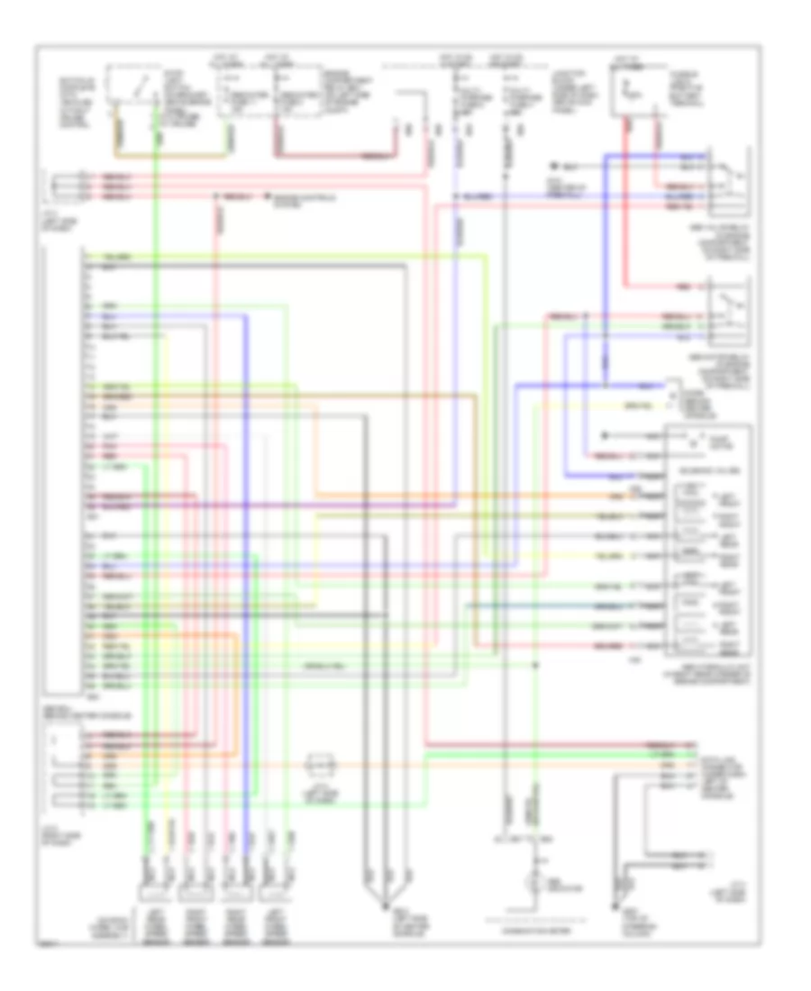
List of elements for Anti-lock Brake Wiring Diagrams for Mitsubishi Mirage DE 1999:
- (on each wheel hub assembly)
- (w/o cruise) (w/ cruise)
- 60a
- A39
- A40
- Abs ecu (behind center console)
- Abs hydraulic unit (in right rear corner of engine compartment)
- Abs indicator
- Abs motor relay (in engine compartment, on right side of firewall)
- Abs valve relay (in engine compartment, on right side of firewall)
- B07
- B08
- B30
- B31
- B60
- B63
- B66
- Combination meter
- Data link connector (under dash, left of center console)
- Dedicated fuse 11 15a
- Dedicated fuse 2 10a
- Diode (behind center console)
- Engine compartment relay box (on left side of engine compt)
- Engine controls system
- Fusible link 8 (positive battery terminal)
- G121 (center of firewall)
- G207 (top of steering column)
- G302 (left side of center console)
- Hot at all times
- Hot in on & start
- Hot in on or start
- J/c 3 (left side of dash)
- J/c 4 (left side of dash)
- J/c 5 (right side of dash)
- Junction block (under left side of dash, above kick panel)
- Left front
- Left front wheel speed sensor
- Left rear
- Left rear wheel speed sensor
- Multi- purpose fuse 4 10a
- Multi- purpose fuse 6 10a
- Nca
- Out
- Pnk
- Pump motor
- Red
- Right front
- Right front wheel speed sensor
- Right rear
- Right rear wheel speed sensor
- Solenoid valves
- Stop- light switch (on bracket, above brake panel)
- Switch is complete with vehicles without cruise control
 English