ANTI-LOCK BRAKES
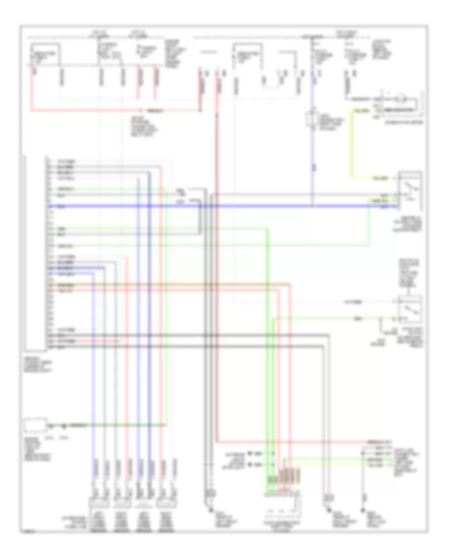
Anti-Lock Brakes Wiring Diagram, 4-Wheel Drive for Mitsubishi Montero Sport LS 2000

List of elements for Anti-Lock Brakes Wiring Diagram, 4-Wheel Drive for Mitsubishi Montero Sport LS 2000:
- (2.4l) (3.0l)
- (in right rear of engine compartment) free-wheeling engage switch
- (on bracket, on each wheel hub)
- (w/ cruise)
- (w/o cruise)
- 1998-99
- 1999-
- 4wd detection switch (on transfer case)
- Abs ecu (in right rear corner of engine compt)
- Abs indicator
- Abs relay (on right rear side of engine compartment)
- C04
- C05
- Combination meter
- D01
- D02
- D06
- D09
- D13
- Data link connector 1 (under left side of dash, near relay box)
- Dedicated fuse 5 10a
- Dedicated fuse 8 10a
- Engine compt relay box (on left inner fender panel)
- Engine control module (1998) (behind right side of dash)
- Exterior lights system (stoplight)
- Fusible link 1 80a 100a
- Fusible link 6 40a
- G-sensor (behind center console)
- G104 (rear of left front fender)
- G105 (rear of right front fender)
- G200 (behind left kick panel)
- Hot at all times
- Hot in run
- Hot in run & start
- Iod or storage connector (in eng compt relay box)
- Joint connector 1 (right side of dash)
- Joint connector 2 (right side of dash)
- Joint connector 3 (right side of dash)
- Joint connector 4 (left side of dash)
- Junction block (behind left side of dash)
- Left front wheel speed sensor
- Left rear wheel speed sensor
- Multi- purpose fuse 11 10a
- Multi- purpose fuse 7 10a
- Nca
- Rear differential circuit
- Red
- Right front wheel speed sensor
- Right rear wheel speed sensor
- Stoplight switch (on bracket, above brake pedal)
- Switch is complete with vehicles without cruise control
Anti-Lock Brakes Wiring Diagram, RWD for Mitsubishi Montero Sport LS 2000
List of elements for Anti-Lock Brakes Wiring Diagram, RWD for Mitsubishi Montero Sport LS 2000:
- (2.4l)
- (2.4l) (3.0l)
- (3.0l)
- (on bracket, on each wheel hub)
- (w/ cruise)
- (w/o cruise)
- 1998-
- Abs ecu (in right rear corner of engine compt)
- Abs indicator
- Abs relay (on right side of engine compartment)
- C04
- C05
- Combination meter
- D01
- D02
- D06
- D09
- D13
- Data link connector 1 (under left side of dash, near relay box)
- Dedicated fuse 5 10a
- Dedicated fuse 8 10a
- Engine compt relay box (on left inner fender panel)
- Engine control module (1998) (behind right side of dash)
- Exterior lights system (stoplight)
- Fusible link 1 80a 100a
- Fusible link 6 40a
- G104 (rear of left front fender)
- G105 (rear of right front fender)
- G200 (behind left kick panel)
- Hot at all times
- Hot in run
- Hot in run & start
- Iod or storage connector (in eng compt relay box)
- Joint connector 1 (right side of dash)
- Joint connector 2 (right side of dash)
- Junction block (behind left side of dash)
- Left front wheel speed sensor
- Left rear wheel speed sensor
- Multi- purpose fuse 11 10a
- Multi- purpose fuse 7 10a
- Nca
- Red
- Right front wheel speed sensor
- Right rear wheel speed sensor
- Stoplight switch (on bracket, above brake pedal)
- Switch is complete with vehicles without cruise control