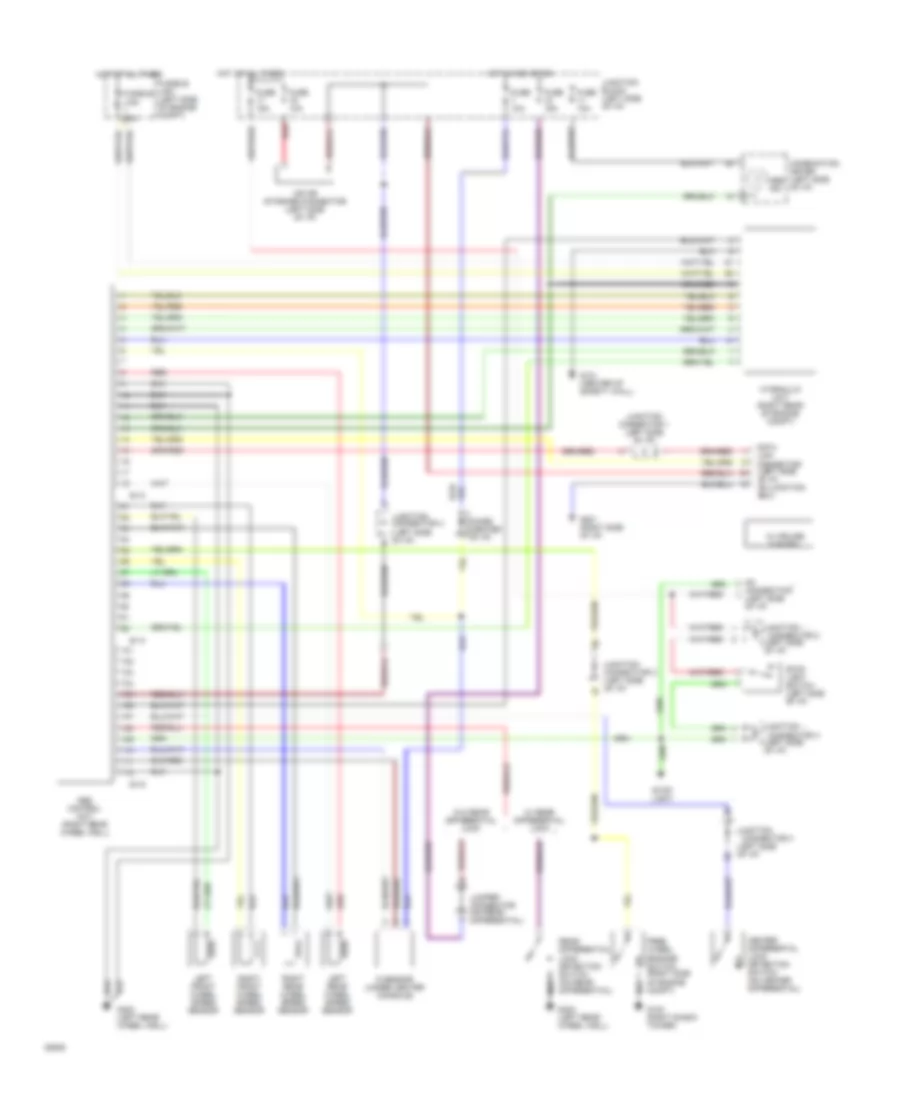
ANTI-LOCK BRAKES
Anti-lock Brake Wiring Diagrams for Mitsubishi Montero SR 1994
List of elements for Anti-lock Brake Wiring Diagrams for Mitsubishi Montero SR 1994:
- (left side of i/p)
- Abs control unit (right rear wheel well)
- Abs ind
- Center differential lock detection switch (on center differential)
- Combination meter (left side of i/p)
- Connector 2
- Connector 3
- Connector 3 (left side of i/p)
- Data link connector (left side of i/p, on junction box)
- Diode (center of i/p)
- E-13
- E-14
- E-15
- Free wheel engage switch (right side of engine compt)
- Fuse 10a
- Fuse 15a
- Fusible
- Fusible link (left side of engine compt)
- G sensor (under center console)
- G103 (right shock tower)
- G121 (center of safety wall)
- G201 (right side of i/p)
- G402 (left rear wheel well)
- Hot at all times
- Hot in acc or on
- Hydraulic unit (right rear of engine compt)
- Iod or storage connector (left side of i/p)
- Jumper connector (on rear differential)
- Junction
- Junction block (left side of i/p)
- Junction connector 1 (left side of i/p)
- Junction connector 3 (left side of i/p)
- Left front wheel speed sensor
- Left rear wheel speed sensor
- Link 60a
- No connection (left side of i/p)
- Rear differential lock detection switch (on rear differential)
- Red
- Right front wheel speed sensor
- Right rear wheel speed sensor
- Stop light
- Stop light switch (left side of i/p)
- W/ cruise control
- W/ rear differential lock
- W/o rear differential lock
 English