ANTI-LOCK BRAKES
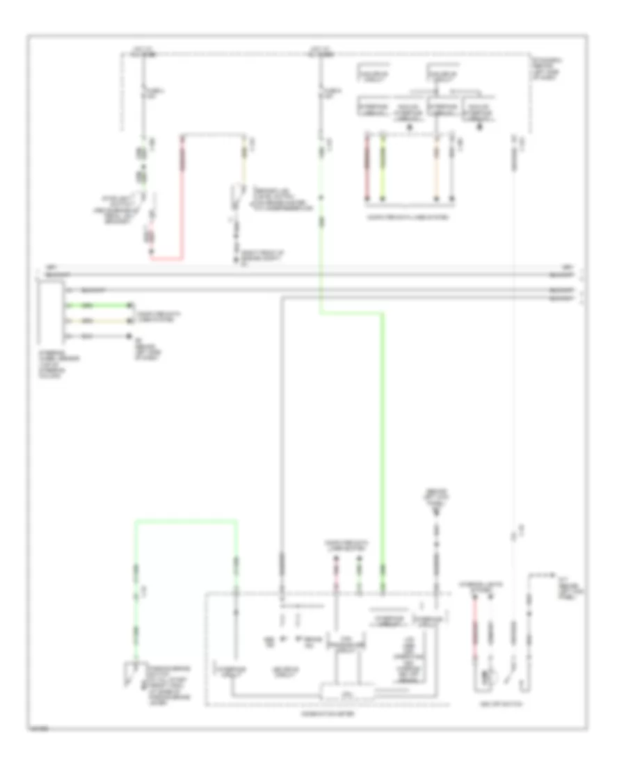
Anti-lock Brakes Wiring Diagram, with Active Skid Control (1 of 3) for Mitsubishi Outlander GT 2010

List of elements for Anti-lock Brakes Wiring Diagram, with Active Skid Control (1 of 3) for Mitsubishi Outlander GT 2010:
- Asc-ecu (right rear of engine compt)
- C-129
- C-315
- C-33
- Computer data lines system
- Engine compartment relay box (left side of engine compt)
- Etacs-ecu (behind left side of dash)
- Fuse 17 10a
- Fusible link 26 40a
- Fusible link 27 30a
- G & yaw rate sensor (under front of center floor console)
- G19 (under left end of dash)
- Hot at all times
- Hydraulic unit
- Left front wheel speed sensor (at left front wheel hub assembly)
- Left rear wheel speed sensor (at left rear wheel hub assembly)
- Motor
- Nca
- Pnk
- Pressure sensor
- Right front wheel speed sensor (at right front wheel hub assembly)
- Right rear wheel speed sensor (at right rear wheel hub assembly)
- Solenoid valve
- Transmissions system
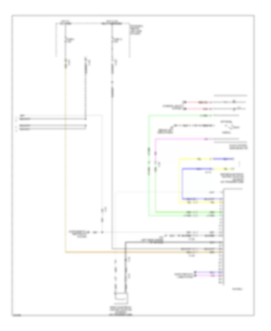
Anti-lock Brakes Wiring Diagram, with Active Skid Control (2 of 3) for Mitsubishi Outlander GT 2010
List of elements for Anti-lock Brakes Wiring Diagram, with Active Skid Control (2 of 3) for Mitsubishi Outlander GT 2010:
- (behind left kick panel) g17
- (right front of engine compt) g1
- Abs ind
- Analog interface circuit
- Asc off switch
- Brake fluid level switch (on brake master cylinder reservoir)
- Brake ind
- C-22
- C-301
- C-304
- C-312
- C-313
- C-317
- C-32
- Can drive circuit
- Can transceiver circuit
- Combination meter
- Computer data lines system
- Cpu
- Etacs-ecu (behind left side of dash)
- Fuse 2 15a
- Fuse 9 15a
- G17 (behind left kick panel)
- G6 (behind left side of dash)
- Hot at all times
- Illum
- Interface circuit
- Interior lights system
- Lcd (abs asc operating asc warning asc off brake)
- Led drive circuit
- Parking brake switch (w/ hill start assist (hsa)) (at base of parking brake lever)
- Pnk
- Steering wheel sensor (top of steering column)
- Stoplight switch (above brake pedal, on bracket)
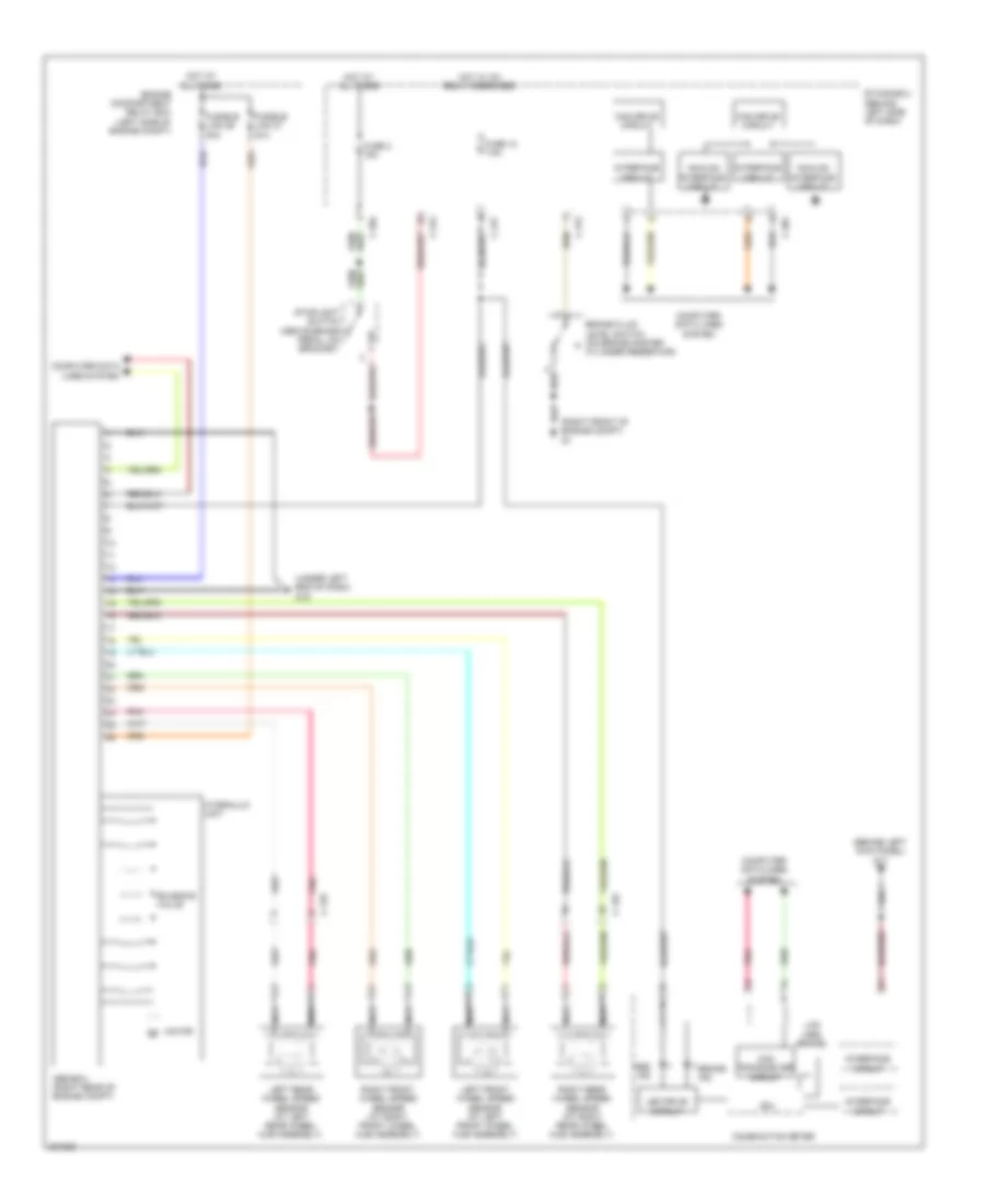
Anti-lock Brakes Wiring Diagram, with Active Skid Control (3 of 3) for Mitsubishi Outlander GT 2010
List of elements for Anti-lock Brakes Wiring Diagram, with Active Skid Control (3 of 3) for Mitsubishi Outlander GT 2010:
- A-13
- Awc-ecu
- C-138
- C-31
- C-311
- C-313
- C-317
- C-32
- C-42
- Center electronic control coupling solenoid (on transfer case)
- Computer data lines system
- D-113
- Etacs-ecu (behind left side of dash)
- Front electronic control coupling solenoid (on transfer case)
- Fuse 12 7.5a
- Fuse 8 7.5a
- G18 (left rear corner of vehicle)
- G6 (behind left side of dash)
- Hot at all times
- Hot w/ ig1 relay energized
- Ill
- Interior lights system
- Normal
- Off road
- Pnk
- S-awc control mode selector
- Snow
Anti-lock Brakes Wiring Diagram, without Active Skid Control for Mitsubishi Outlander GT 2010
List of elements for Anti-lock Brakes Wiring Diagram, without Active Skid Control for Mitsubishi Outlander GT 2010:
- (behind left kick panel) g17
- (right front of engine compt) g1
- (under left end of dash) g19
- Abs ind
- Abs-ecu (right rear of engine compt)
- Analog interface circuit
- Brake fluid level switch (on brake master cylinder reservoir)
- Brake ind
- C-129
- C-301
- C-304
- C-312
- C-317
- Can drive circuit
- Can transceiver circuit
- Combination meter
- Computer data lines system
- Cpu
- Engine compartment relay box (left side of engine compt)
- Etacs-ecu (behind left side of dash)
- Fuse 12 7.5a
- Fuse 2 15a
- Fusible link 26 40a
- Fusible link 27 30a
- Hot at all times
- Hot w/ ig1 relay energized
- Hydraulic unit
- Interface circuit
- Lcd (abs brake)
- Led drive circuit
- Left front wheel speed sensor (at left front wheel hub assembly)
- Left rear wheel speed sensor (at left rear wheel hub assembly)
- Motor
- Nca
- Pnk
- Right front wheel speed sensor (at right front wheel hub assembly)
- Right rear wheel speed sensor (at right rear wheel hub assembly)
- Solenoid valve
- Stoplight switch (above brake pedal, on bracket)