ANTI-LOCK BRAKES
Anti-lock Brakes Wiring Diagram (1 of 2) for Mitsubishi Outlander SE 2014

List of elements for Anti-lock Brakes Wiring Diagram (1 of 2) for Mitsubishi Outlander SE 2014:
- (left kick panel) j/c 6 (c-28)
- Asc-ecu (right rear of engine compt)
- C-126
- C-129
- Computer data lines system
- D-124
- D-125
- Engine compartment relay box (left side of engine compt)
- Fusible link sbf5 40a
- Fusible link sbf7 30a
- G & yaw rate sensor
- G16 (behind center of dash)
- Hot at all times
- Hydraulic unit
- J/c 7 (d124 & d125)
- Left front wheel speed sensor (at left front wheel hub assembly)
- Left rear wheel speed sensor (at left rear wheel hub assembly)
- Motor
- Nca
- Pnk
- Pressure sensor
- Red
- Right front wheel speed sensor (at right front wheel hub assembly)
- Right rear wheel speed sensor (at right rear wheel hub assembly)
- Solenoid valve
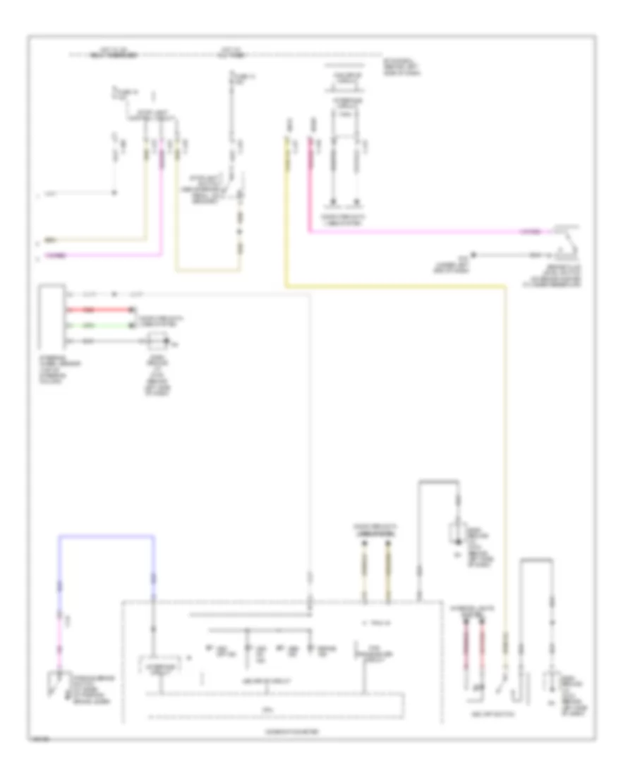
Anti-lock Brakes Wiring Diagram (2 of 2) for Mitsubishi Outlander SE 2014
List of elements for Anti-lock Brakes Wiring Diagram (2 of 2) for Mitsubishi Outlander SE 2014:
- (behind left side of dash)
- Abs ind
- Asc off ind
- Asc off switch
- Asc on ind
- Ascs
- Bfsw
- Brake fluid level switch (on brake master cylinder reservoir)
- Brake ind
- C-24
- C-402
- C-413
- C-416
- C-417
- C-419
- C-421
- Can drive circuit
- Can transceiver circuit
- Combination meter
- Computer data lines system
- Cpu
- Dash ground j/c (c-30)
- Dash ground j/c (c-30) (behind left side of dash)
- Etacs-ecu (behind left side of dash)
- Fuse 14 15a
- Fuse 15 10a
- G19 (under left end of dash)
- Hot at all times
- Hot w/ ig1 relay energized
- Ill
- Interface circuit
- Interior lights system
- Led drive circuit
- Parking brake switch (at base of parking brake lever)
- Red
- Steering wheel sensor (top of steering column)
- Stop light control circuit
- Stoplight switch (above brake pedal, on bracket)