ANTI-LOCK BRAKES
Anti-lock Brake Wiring Diagrams for Nissan 240SX LE 1997
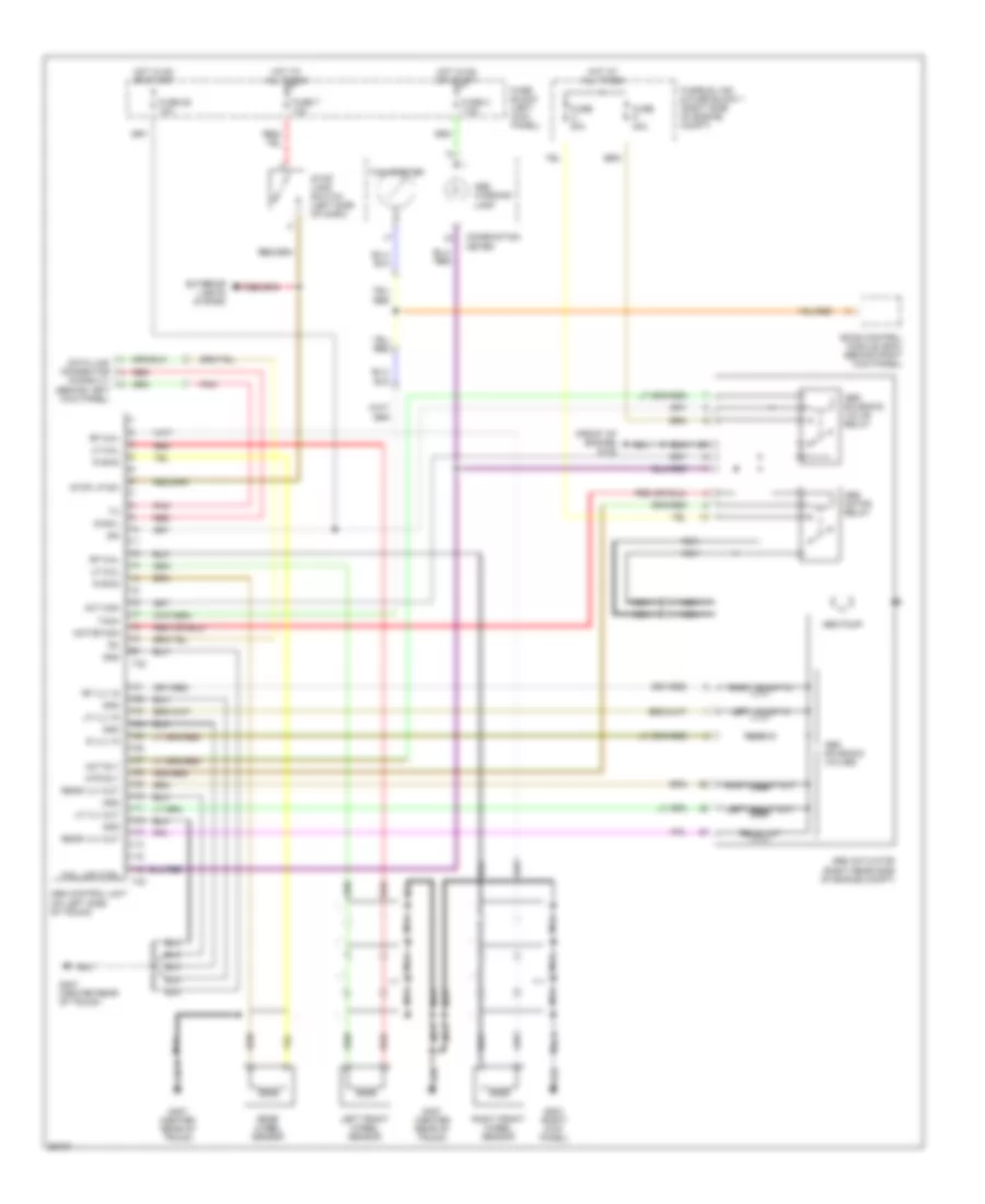
List of elements for Anti-lock Brake Wiring Diagrams for Nissan 240SX LE 1997:
- (front of engine) g125
- Abs actuator (right rear side of engine compt)
- Abs control unit (on left side of trunk)
- Abs motor relay
- Abs pump
- Abs solenoid valve relay
- Abs solenoid valves
- Abs warning lamp
- Act mon
- Act rly
- Combination meter
- Data link connector (consult) (behind left kick panel)
- Diag-l
- Eccs control module (ecm) (behind right kick panel)
- Exterior lights system
- Fail lmp ctrl
- Fuse 2 7.5a
- Fuse 26 10a
- Fuse 7 10a
- Fuse block (left kick panel)
- Fuse o 30a
- Fuse p 30a
- Fusible link & fuse block 1 (right side of engine compt)
- G203 (right kick panel)
- G407 (center rear of trunk)
- Gnd
- Hot at all times
- Hot in on or start
- Ign
- Left front in
- Left front out
- Left front wheel sensor
- Lf vlv in
- Lf vlv out
- Lf whl
- Motor mon
- Mtr rly
- Nca
- Pnk
- R skid
- R vlv in
- Rear in
- Rear out
- Rear vlv out
- Rear wheel sensor
- Red
- Rf vlv in
- Rf whl
- Right front in
- Right front out
- Right front wheel sensor
- Stop lamp switch (left side of dash)
- Stop lp sw
- T32
- T33
- Tach
- Tachometer
 English