ANTI-LOCK BRAKES
Anti-lock Brakes Wiring Diagram, Coupe (1 of 2) for Nissan Altima 2012

List of elements for Anti-lock Brakes Wiring Diagram, Coupe (1 of 2) for Nissan Altima 2012:
- (behind right end of dash) m61
- 12m m5
- 1p e6
- 67g m1
- 75g
- Abs actuator & electric unit (control unit) (right rear of engine compt)
- Abs/tcs/vdc control unit
- Actuator
- Asr aus
- B10
- B43
- Bls
- Can-h
- Can-l
- Can-m2
- Can-p2
- Computer data lines system
- Diag-k
- Dp fl
- Dp fr
- Dp rl
- Dp rr
- Ds fl
- Ds fr
- Ds rl
- Ds rr
- E18
- E29
- E30
- E33
- E44
- E46
- E47
- E49
- E6 8p
- Fl in
- Fl out
- Fr in
- Fr out
- Fuse & fusible link box (left front of engine compt, near ipdm e/r)
- Fuse 10a
- Fuse block (j/b) (behind left end of dash)
- Fusible link f 50a
- Fusible link g 30a
- Gnd
- Hot at all times
- Hot in on or start
- Hsv 1
- Hsv 2
- Interior lights system
- Ipdm e/r (intelligent power distribution module engine room) (left side of engine compt)
- J/c m01 (behind left side of dash)
- Junction block e44, e46 e47 & e49
- Left front wheel sensor (at left front wheel hub assembly)
- Left rear wheel sensor (at left rear hub assembly)
- Motor
- Motor relay
- Pnk
- Red
- Relay unit
- Right front wheel sensor (at right front wheel hub assembly)
- Right rear wheel sensor (at right rear hub assembly)
- Rl in
- Rl out
- Rr in
- Rr out
- Solenoid valve relay
- Usv1
- Usv2
- Vdc off switch
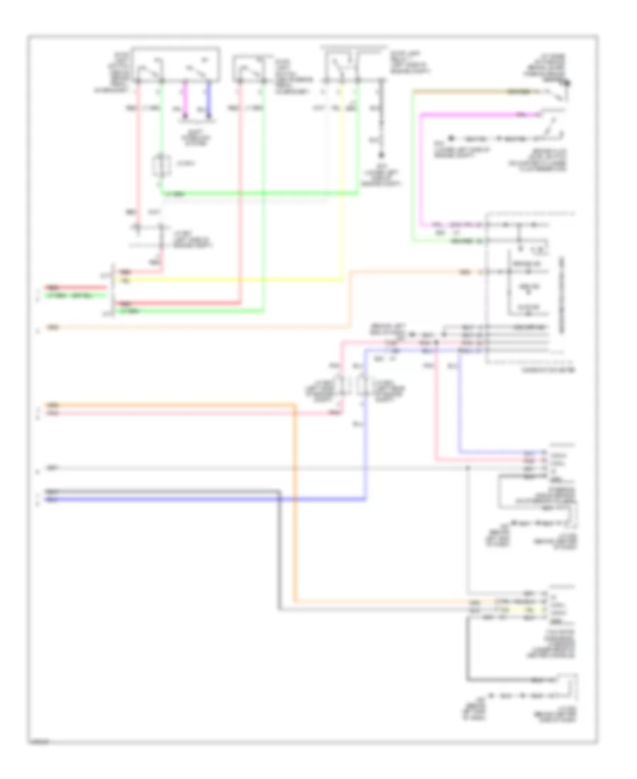
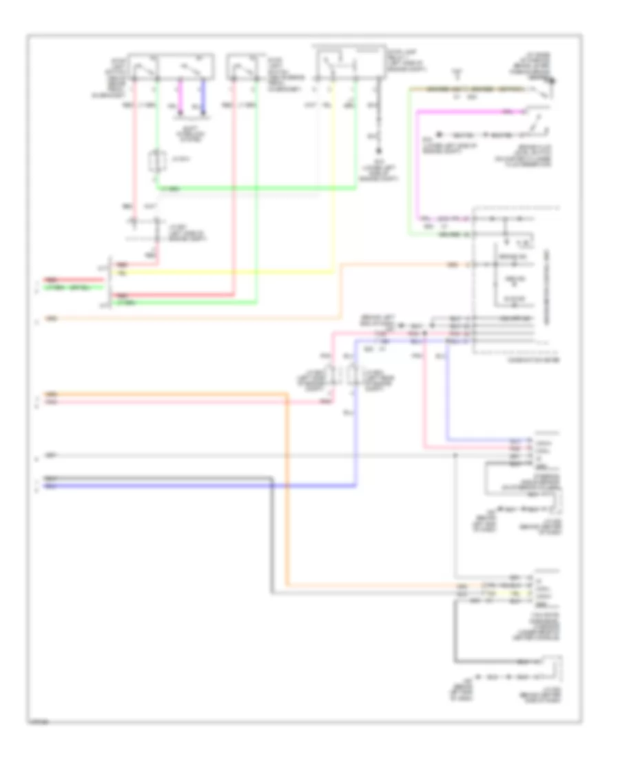
Anti-lock Brakes Wiring Diagram, Coupe (2 of 2) for Nissan Altima 2012
List of elements for Anti-lock Brakes Wiring Diagram, Coupe (2 of 2) for Nissan Altima 2012:
- (at base of parking brake lever) parking brake switch
- (behind left end of dash) m57
- 15g
- 31g
- 70g
- 77g
- Abs ind
- Brake fluid level switch (on master cylinder fluid reservoir)
- Brake ind
- Can-h
- Can-l
- Combination meter
- Cvt
- E15 (lower left side of engine compt)
- E30
- Gnd
- J/c e03 (left rear of engine compt)
- J/c e04 (left side of engine compt)
- J/c e07 (left side of engine compt)
- J/c e14
- J/c m02 (behind center of dash)
- J/c m02 (behind center side of dash)
- M/t
- M57 (behind left end of dash)
- Pnk
- Red
- Shift interlock system
- Slip ind
- Steering angle sensor (on steering column)
- Stop lamp relay 1 (left side of engine compt)
- Stop light switch (above brake pedal, on bracket)
- Unified meter control unit
- Vdc off ind
- Yaw rate/ side/decel g sensor (under rear of center console)
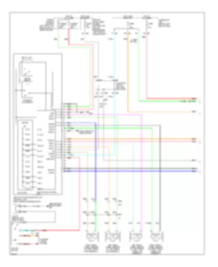
Anti-lock Brakes Wiring Diagram, Sedan with VDC (1 of 2) for Nissan Altima 2012
List of elements for Anti-lock Brakes Wiring Diagram, Sedan with VDC (1 of 2) for Nissan Altima 2012:
- (behind right end of dash) m61
- 12m m5
- 1p e6
- 67g m1
- 75g
- Abs actuator & electric unit (control unit) (right rear of engine compt)
- Abs/tcs/vdc control unit
- Actuator
- Asr aus
- B10
- B43
- Bls
- Can-h
- Can-l
- Can-m2
- Can-p2
- Computer data lines system
- Diag-k
- Dp fl
- Dp fr
- Dp rl
- Dp rr
- Ds fl
- Ds fr
- Ds rl
- Ds rr
- E18
- E29
- E30
- E33
- E44
- E46
- E47
- E49
- E6 8p
- Fl in
- Fl out
- Fr in
- Fr out
- Fuse & fusible link box (left front of engine compt, near ipdm e/r)
- Fuse 10a
- Fuse block (j/b) (behind left end of dash)
- Fusible link f 50a
- Fusible link g 30a
- Gnd
- Hot at all times
- Hot in on or start
- Hsv 1
- Hsv 2
- Interior lights system
- Ipdm e/r (intelligent power distribution module engine room) (left side of engine compt)
- J/c m01 (behind left side of dash)
- Junction block e44, e46 e47 & e49
- Left front wheel sensor (at left front wheel hub assembly)
- Left rear wheel sensor (at left rear hub assembly)
- Motor
- Motor relay
- Pnk
- Red
- Relay unit
- Right front wheel sensor (at right front wheel hub assembly)
- Right rear wheel sensor (at right rear hub assembly)
- Rl in
- Rl out
- Rr in
- Rr out
- Solenoid valve relay
- Usv1
- Usv2
- Vdc off switch
Anti-lock Brakes Wiring Diagram, Sedan with VDC (2 of 2) for Nissan Altima 2012
List of elements for Anti-lock Brakes Wiring Diagram, Sedan with VDC (2 of 2) for Nissan Altima 2012:
- (at base of parking brake lever) parking brake switch
- (behind left end of dash) m57
- (or pnk)
- 15g
- 31g
- 70g
- 77g
- Abs ind
- Brake fluid level switch (on master cylinder fluid reservoir)
- Brake ind
- Can-h
- Can-l
- Combination meter
- Cvt
- E15 (lower left side of engine compt)
- E30
- Gnd
- J/c e03 (left rear of engine compt)
- J/c e04 (left side of engine compt)
- J/c e07 (left side of engine compt)
- J/c e14
- J/c m02 (behind center of dash)
- J/c m02 (behind center side of dash)
- M/t
- M57 (behind left end of dash)
- Pnk
- Red
- Shift interlock system
- Slip ind
- Steering angle sensor (on steering column)
- Stop lamp relay 1 (left side of engine compt)
- Stop light switch (above brake pedal, on bracket)
- Unified meter control unit
- Vdc off ind
- Yaw rate/ side/decel g sensor (under rear of center console)
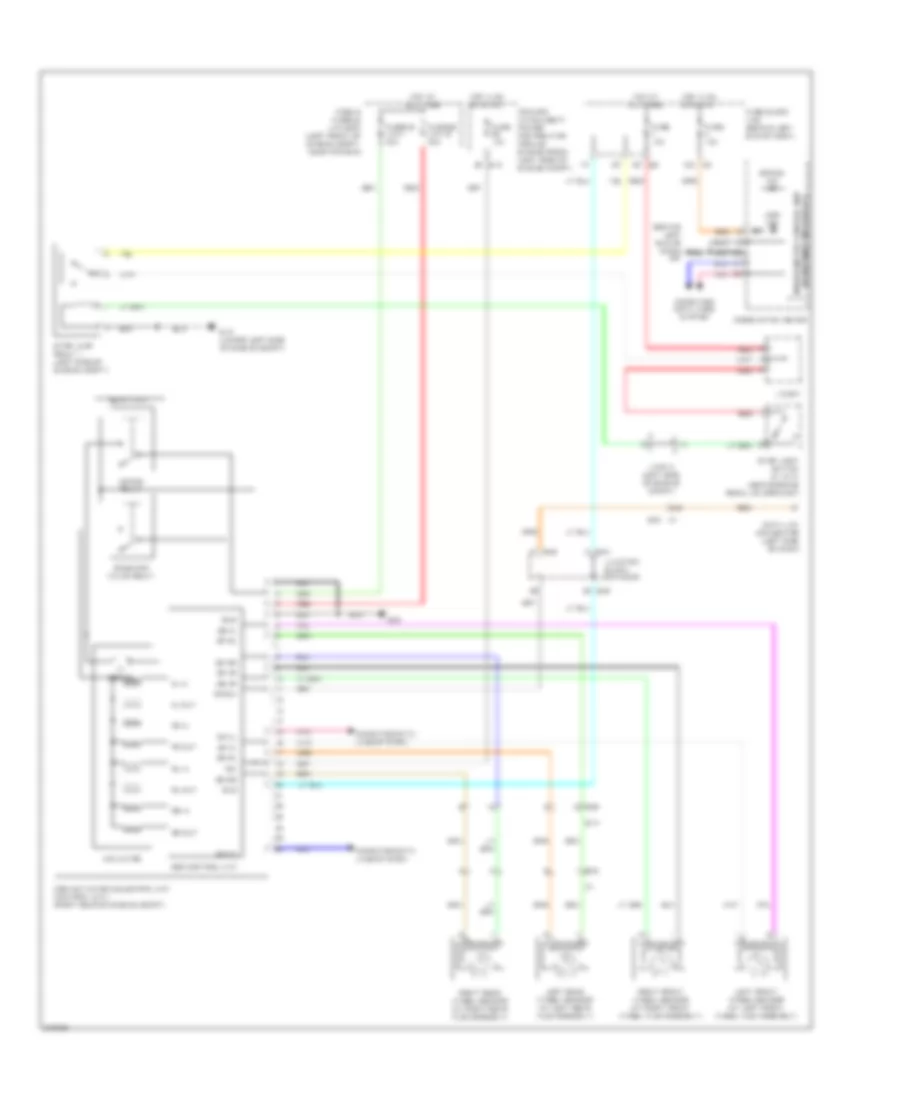
Anti-lock Brakes Wiring Diagram, Sedan without VDC for Nissan Altima 2012
List of elements for Anti-lock Brakes Wiring Diagram, Sedan without VDC for Nissan Altima 2012:
- (behind left end of dash) m57
- (w/ information display) unified meter control unit
- 12m m5
- 34g
- 8p e6
- Abs actuator & electric unit (control unit) (right rear of engine compt)
- Abs control unit
- Abs ind
- Actuator
- B10
- B43
- Bls
- Brake ind
- Can-h
- Can-l
- Combination meter
- Computer data lines system
- Data link connector (left side of dash)
- Diag-k
- Dp fl
- Dp fr
- Dp rl
- Dp rr
- Ds fl
- Ds fr
- Ds rl
- Ds rr
- E15 (lower left side of engine compt)
- E18
- E29
- E30
- E33
- E44
- E46
- Fl in
- Fl out
- Fr in
- Fr out
- Fuse & fusible link box (left front of engine compt, near ipdm e/r)
- Fuse 10a
- Fuse block (j/b) (behind left end of dash)
- Fusible link g 30a
- Fusible link i 40a
- Gnd
- Hot at all times
- Hot in on or start
- Ign
- Ipdm e/r (intelligent power distribution module engine room) (left side of engine compt)
- J/c e07
- J/c e14 (left side of engine compt)
- Junction block e44 & e46
- Left front wheel sensor (at left front wheel hub assembly)
- Left rear wheel sensor (at left rear hub assembly)
- Motor
- Motor relay
- Pnk
- Red
- Relay unit
- Right front wheel sensor (at right front wheel hub assembly)
- Right rear wheel sensor (at right rear hub assembly)
- Rl in
- Rl out
- Rr in
- Rr out
- Solenoid valve relay
- Stop lamp relay 1 (left side of engine compt)
- Stop light switch (w/ cvt) (above brake pedal, on bracket)