ANTI-LOCK BRAKES
Anti-lock Brake Wiring Diagrams for Nissan Altima S 2002
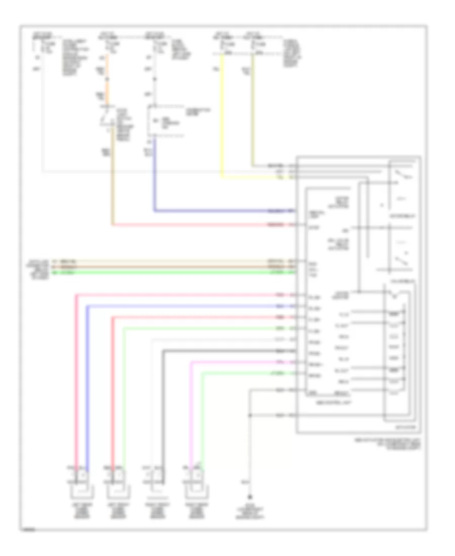
List of elements for Anti-lock Brake Wiring Diagrams for Nissan Altima S 2002:
- (below left side of dash)
- Abs actuator and electric unit (on lower right rear of engine compt)
- Abs control unit
- Abs fail lamp
- Abs warning ind
- Actuator
- Combination meter
- Connector
- Data link
- Dia l
- E126 (lower right rear of engine compt)
- Fl in
- Fl out
- Fl ss -
- Fr in
- Fr out
- Fr ss -
- Fuse & fusible link box (on left front of engine compt)
- Fuse 10a
- Fuse block (behind left side of dash)
- Fuse i 40a
- Fuse j 40a
- Gnd
- Hot at all times
- Hot in on or start
- Ign
- Intelligent power distribution module engine room (on right front of engine compt)
- Left front wheel speed sensor
- Left rear wheel speed sensor
- Motor monitor
- Motor relay
- Motor relay actuator
- Nca
- Pnk
- Red
- Right front wheel speed sensor
- Right rear wheel speed sensor
- Rl in
- Rl out
- Rl ss -
- Rr in
- Rr out
- Rr ss +
- Rr ss -
- Rxd
- Sol valve relay actuator
- Stop
- Stop light switch (on bracket above brake pedal)
- Txd
- Valve relay
 English