ANTI-LOCK BRAKES
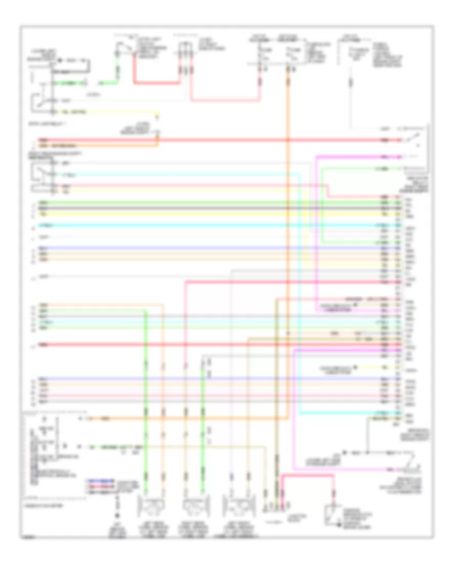
Anti-lock Brakes Wiring Diagram, Except Hybrid with Traction Control (1 of 2) for Nissan Altima S 2011

List of elements for Anti-lock Brakes Wiring Diagram, Except Hybrid with Traction Control (1 of 2) for Nissan Altima S 2011:
- (behind right end of dash) m61
- 12m m5
- 1p e6
- 67g m1
- 75g
- Abs actuator & electric unit (control unit) (right rear of engine compt)
- Abs/tcs/vdc control unit
- Actuator
- Asr aus
- B10
- B43
- Bls
- Can-h
- Can-l
- Can-m2
- Can-p2
- Computer data lines system
- Diag-k
- Dp fl
- Dp fr
- Dp rl
- Dp rr
- Ds fl
- Ds fr
- Ds rl
- Ds rr
- E18
- E29
- E30
- E33
- E44
- E46
- E47
- E49
- E6 8p
- Fl in
- Fl out
- Fr in
- Fr out
- Fuse & fusible link box (left front of engine compt, near ipdm e/r)
- Fuse 10a
- Fuse block (j/b) (behind left end of dash)
- Fusible link f 50a
- Fusible link g 30a
- Gnd
- Hot at all times
- Hot in on or start
- Hsv 1
- Hsv 2
- Interior lights system
- Ipdm e/r (intelligent power distribution module engine room) (left side of engine compt)
- J/c m01 (behind left side of dash)
- Junction block
- Left front wheel sensor (at left front wheel hub assembly)
- Left rear wheel sensor (at left rear hub assembly)
- Motor
- Motor relay
- Pnk
- Red
- Relay unit
- Right front wheel sensor (at right front wheel hub assembly)
- Right rear wheel sensor (at right rear hub assembly)
- Rl in
- Rl out
- Rr in
- Rr out
- Solenoid valve relay
- U sv1
- U sv2
- Vdc off switch
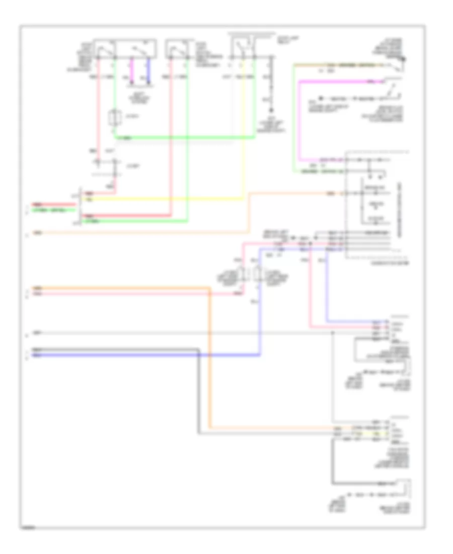
Anti-lock Brakes Wiring Diagram, Except Hybrid with Traction Control (2 of 2) for Nissan Altima S 2011
List of elements for Anti-lock Brakes Wiring Diagram, Except Hybrid with Traction Control (2 of 2) for Nissan Altima S 2011:
- (at base of parking brake lever) parking brake switch
- (behind left end of dash) m57
- (or pnk)
- 15g
- 31g
- 70g
- 77g
- Abs ind
- Brake fluid level switch (on master cylinder fluid reservoir)
- Brake ind
- Can-h
- Can-l
- Combination meter
- Cvt
- E15 (lower left side of engine compt)
- E30
- E30 m1
- Gnd
- J/c e03 (left rear of engine compt)
- J/c e04 (left side of engine compt)
- J/c e07
- J/c e14
- J/c m02 (behind center of dash)
- J/c m02 (behind center side of dash)
- M/t
- M57 (behind left end of dash)
- Pnk
- Red
- Shift interlock system
- Slip ind
- Steering angle sensor (on steering column)
- Stop lamp relay
- Stop light switch (above brake pedal, on bracket)
- Unified meter control unit
- Vdc off ind
- Yaw rate/ side/decel g sensor (under rear of center console)
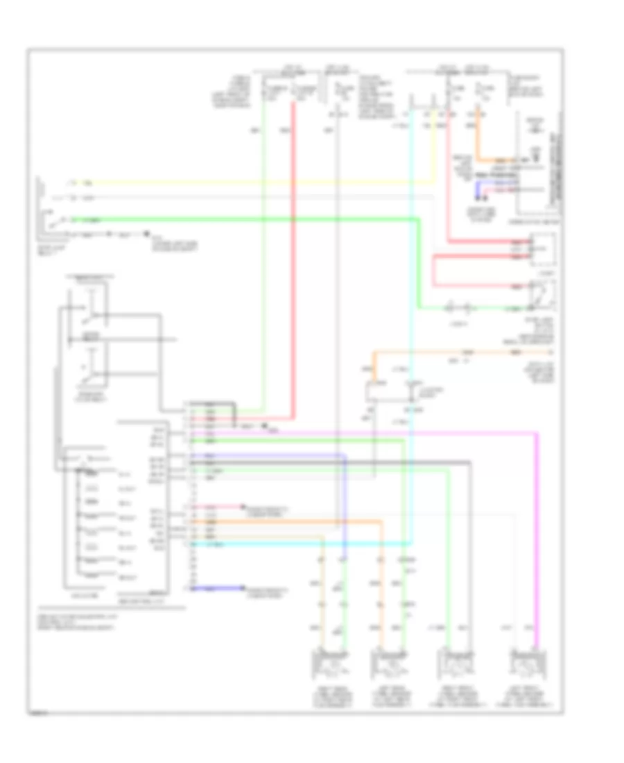
Anti-lock Brakes Wiring Diagram, Except Hybrid without Traction Control for Nissan Altima S 2011
List of elements for Anti-lock Brakes Wiring Diagram, Except Hybrid without Traction Control for Nissan Altima S 2011:
- (behind left end of dash) m57
- (w/ information display) unified meter control unit
- 12m m5
- 34g
- 8p e6
- Abs actuator & electric unit (control unit) (right rear of engine compt)
- Abs control unit
- Abs ind
- Actuator
- B10
- B43
- Bls
- Brake ind
- Can-h
- Can-l
- Combination meter
- Computer data lines system
- Data link connector (left side of dash)
- Diag-k
- Dp fl
- Dp fr
- Dp rl
- Dp rr
- Ds fl
- Ds fr
- Ds rl
- Ds rr
- E15 (lower left side of engine compt)
- E18
- E29
- E30
- E33
- E44
- E46
- Fl in
- Fl out
- Fr in
- Fr out
- Fuse & fusible link box (left front of engine compt, near ipdm e/r)
- Fuse 10a
- Fuse block (j/b) (behind left end of dash)
- Fusible link g 30a
- Fusible link i 40a
- Gnd
- Hot at all times
- Hot in on or start
- Ign
- Ipdm e/r (intelligent power distribution module engine room) (left side of engine compt)
- J/c e07
- J/c e14
- Junction block
- Left front wheel sensor (at left front wheel hub assembly)
- Left rear wheel sensor (at left rear hub assembly)
- Motor
- Motor relay
- Pnk
- Red
- Relay unit
- Right front wheel sensor (at right front wheel hub assembly)
- Right rear wheel sensor (at right rear hub assembly)
- Rl in
- Rl out
- Rr in
- Rr out
- Solenoid valve relay
- Stop lamp relay 1
- Stop light switch (w/ cvt) (above brake pedal, on bracket)
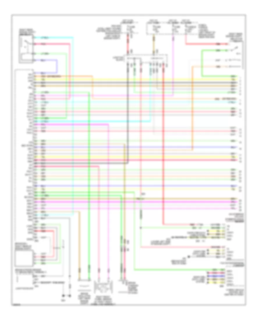
Anti-lock Brakes Wiring Diagram, Hybrid (1 of 3) for Nissan Altima S 2011
List of elements for Anti-lock Brakes Wiring Diagram, Hybrid (1 of 3) for Nissan Altima S 2011:
- (on steering column) steering angle sensor
- (right rear engine compt) abs motor relay 1
- (right rear engine compt) abs relay 1
- 68g
- 69g
- 75g
- 76g m1
- 77g
- B+cty
- B2o
- Brake ecu (right rear of engine compt)
- Brake simulator (left rear engine compt)
- Brake stroke sensor (at brake pedal assembly)
- Brake warning buzzer (center of dash)
- Bs1
- Bso1
- Bso3
- Bz (sig)
- Bzo (pwr)
- Can-h
- Can-l
- Cbi1
- Cin
- Computer data lines system
- Cout
- Di1
- Do1
- E15 (lower left side of engine compt)
- E18
- E24
- E30
- E44
- E45
- E46
- E47
- E50
- E60
- E62
- E66
- Fr+
- Fr-
- Fra+
- Fra-
- Frr+
- Frr-
- Fuse & fusible link box (left front of engine compt, near ipdm e/r)
- Fuse 10a
- Fuse 15a
- Fusible link i 30a
- Gnd
- Hot at all times
- Hot in on or start
- Hybrid vehicle control ecu (center of dash)
- Ig1
- Ipdm e/r (intelligent power distribution module engine room) (left side of engine compt)
- Junction block
- M1 e30
- M61 (behind right end of dash)
- Mr1
- Mtt
- Pac1
- Pck1
- Pfr
- Pmc1
- Pnk
- Prl
- R1+
- R1-
- R3+
- Red
- Right front wheel sensor (at right front wheel hub assembly)
- Rl+
- Rl-
- Rla+
- Rla-
- Rlr+
- Rlr-
- Skg
- Sks
- Sks2
- Smc1
- Sp1
- Spd1
- Stp
- Vcm1
- Vcsk
- Yaw rate/side/decel g sensor
Anti-lock Brakes Wiring Diagram, Hybrid (2 of 3) for Nissan Altima S 2011
List of elements for Anti-lock Brakes Wiring Diagram, Hybrid (2 of 3) for Nissan Altima S 2011:
- (in left "b" pillar) left front door switch
- +bcty
- 17j
- B109
- B117 (at right "c" pillar)
- B129
- Brake actuator (right rear engine compt)
- Brake capacitor (right side of luggage compt)
- Cty
- E24
- E44
- E45
- E46
- E71
- Ena
- Fail
- Gnd
- Junction block
- M10 b104
- Motor
- Out
- Out2
- Pnk
- Red
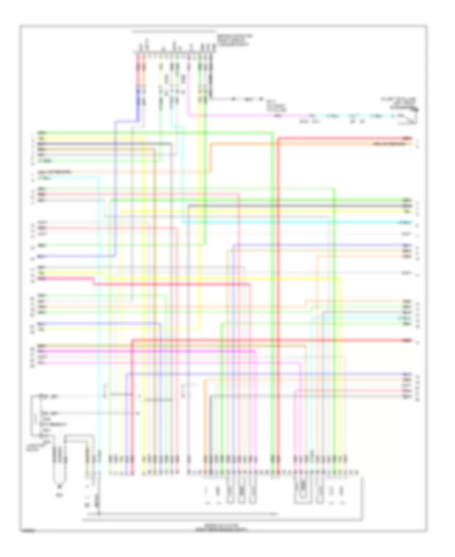
Anti-lock Brakes Wiring Diagram, Hybrid (3 of 3) for Nissan Altima S 2011
List of elements for Anti-lock Brakes Wiring Diagram, Hybrid (3 of 3) for Nissan Altima S 2011:
- (lower left side of engine compt) e15
- (or pnk)
- (right rear engine compt) abs relay 2
- 12m
- 24g
- 74g
- Abs ind
- Abs motor relay 2 (right rear engine compt)
- B10
- B43
- Brake ecu (right rear of engine compt)
- Brake fluid level switch (on master cylinder fluid reservoir)
- Brake ind
- Bs02
- Bs2
- Can-h
- Can-l
- Cb12
- Combination meter
- Computer data lines system
- D12
- Do2
- E15 (lower left side of engine compt)
- E29
- E30
- E47
- E49
- E61
- Electronically control brake ind
- Fl+
- Fl-
- Fla+
- Fla-
- Flr+
- Flr-
- Fuse & fusible link box (left front of engine compt, near ipdm e/r)
- Fuse 10a
- Fuse block (j/b) (behind left end of dash)
- Fusible link h 50a
- Gnd
- Hot at all times
- Hot in on or start
- Ig2
- J/c e04 (left side of engine compt)
- J/c e07 (at right side of dash)
- J/c e14
- Junction block
- Lbl
- Left front wheel sensor (at left front
- Left rear wheel sensor (at left rear wheel hub)
- M1 e30
- M57 (behind left end of dash)
- Mr2
- Parking brake switch (at base of parking brake lever)
- Pck2
- Pfl
- Pkb
- Pmc2
- Pnk
- Prr
- R2+
- R2-
- R4+
- Red
- Right rear wheel sensor (at right rear wheel hub)
- Rr+
- Rr-
- Rra+
- Rra-
- Rrr+
- Rrr-
- Slip ind
- Smc2
- Stop lamp relay 1
- Stop light switch (above brake pedal, on bracket)
- Unified meter control unit (w/ information display)
- Vdc ind
- Vmc2
- Wheel hub assembly)