ANTI-LOCK BRAKES
Anti-lock Brakes Wiring Diagram, with Traction Control for Nissan Altima SL 2003

List of elements for Anti-lock Brakes Wiring Diagram, with Traction Control for Nissan Altima SL 2003:
- (below left side of dash) data link connector
- 10a
- Abs actuator & electric unit (on lower right rear of engine compartment)
- Abs fail lamp
- Abs warning ind
- Abs/tcs control unit
- Actuator
- Combination meter
- Computer datalines system
- Dia l
- E124
- E126 (near abs actuator)
- E30
- Fl in
- Fl out
- Fl ss +
- Fl ss -
- Fr in
- Fr out
- Fr ss +
- Fr ss -
- Fuse
- Fuse & fusible link box (on left front of engine compartment, near battery)
- Fuse 10a
- Fuse block (j/b) (behind left side of dash)
- Fusible link g 30a
- Fusible link h 30a
- Gnd
- Hot at all times
- Hot in on or start
- Ign
- Illum
- Intelligent power distribution module engine room (on right front of engine compt, behind headlight)
- Interior lights system
- Joint connector 3 (behind upper right side of dash)
- K-line
- Left front wheel sensor (on left front wheel hub assembly)
- Left rear wheel sensor (on left rear wheel hub assembly)
- M23
- M24
- M57 (behind right side of dash)
- Motor monitor
- Motor relay
- Motor relay actuator
- Nca
- Pnk
- Red
- Relay unit
- Right front wheel sensor (on right front wheel hub assembly)
- Right rear wheel sensor (on right rear wheel hub assembly)
- Rl in
- Rl out
- Rl ss +
- Rl ss -
- Rr in
- Rr out
- Rr ss +
- Rr ss -
- Slip
- Sol valve relay actuator
- Solenoid valve relay
- Stop
- Stop- light switch (above brake pedal, on bracket)
- Tcs off
- Tcs on/of switch
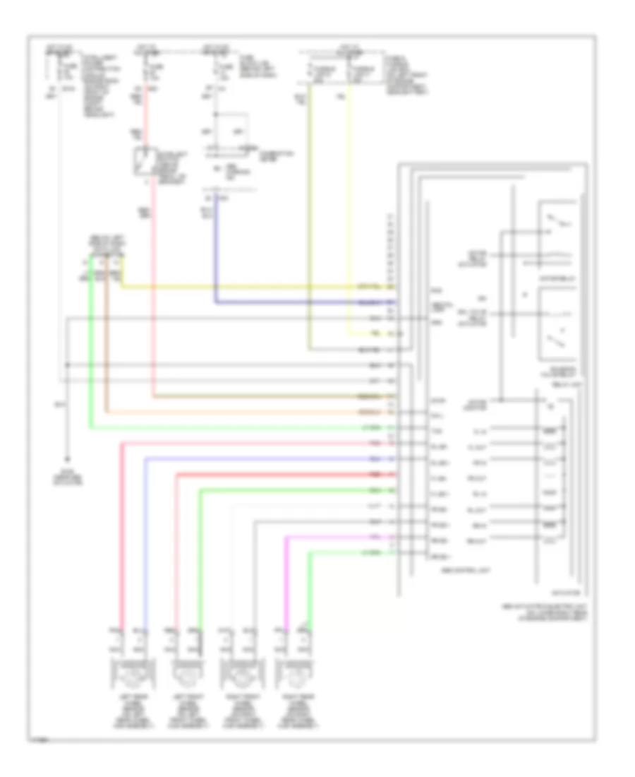
Anti-lock Brakes Wiring Diagram, without Traction Control for Nissan Altima SL 2003
List of elements for Anti-lock Brakes Wiring Diagram, without Traction Control for Nissan Altima SL 2003:
- (below left side of dash) data link connector
- Abs actuator & electric unit (on lower right rear of engine compartment)
- Abs control unit
- Abs fail lamp
- Abs warning ind
- Actuator
- Combination meter
- Dia l
- E124
- E126 (near abs actuator)
- E30
- Fl in
- Fl out
- Fl ss +
- Fl ss -
- Fr in
- Fr out
- Fr ss +
- Fr ss -
- Fuse & fusible link box (on left front of engine compartment, near battery)
- Fuse 10a
- Fuse block (j/b) (behind left side of dash)
- Fusible link g 30a
- Fusible link h 30a
- Gnd
- Hot at all times
- Hot in on or start
- Ign
- Intelligent power distribution module engine room (on right front of engine compt, behind headlight)
- Left front wheel sensor (on left front wheel hub assembly)
- Left rear wheel sensor (on left rear wheel hub assembly)
- M23
- M24
- Motor monitor
- Motor relay
- Motor relay actuator
- Nca
- Pnk
- Red
- Relay unit
- Right front wheel sensor (on right front wheel hub assembly)
- Right rear wheel sensor (on right rear wheel hub assembly)
- Rl in
- Rl out
- Rl ss +
- Rl ss -
- Rr in
- Rr out
- Rr ss +
- Rr ss -
- Rxd
- Sol valve relay actuator
- Solenoid valve relay
- Stop
- Stoplight switch (above brake pedal, on bracket)
- Txd