ANTI-LOCK BRAKES
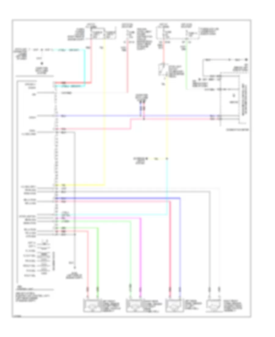
Anti-lock Brakes Wiring Diagram for Nissan Frontier SE 2010
List of elements for Anti-lock Brakes Wiring Diagram for Nissan Frontier SE 2010:
- (w/ information display) unified meter control unit
- Abs actuator & electric unit (control unit) (left rear corner of engine compt)
- Abs control unit
- Abs ind
- Can-h
- Can-l
- Combination meter
- Computer data lines system
- Data link connector (under left side of dash)
- Diag-k
- E119
- E126 (left side of engine compt)
- E160
- Exterior lights system
- Fl in sol
- Fl out sol
- Fr in sol
- Fr lh pwr
- Fr lh sig
- Fr out sol
- Fr rh pwr
- Fr rh sig
- Fuse & fusible link box (right rear of engine compt)
- Fuse 10a
- Fuse 14 10a
- Fuse block (j/b) (under right side of dash)
- Fusible link l 30a
- Fusible link n 40a
- Hot at all times
- Hot in on or start
- Ign
- Ipdm e/r (intelligent power distribution module engine room) (right rear of engine compt)
- Left front wheel sensor (on left front wheel knuckle assembly)
- Left rear wheel sensor (at left wheelwell)
- M57 (behind left side of dash)
- M61 (behind right side of dash)
- Mot (+)
- Mot (-)
- Mtr gnd
- Mtr sply
- Pnk
- R in sol
- R out sol
- Red
- Right front wheel sensor (on right front wheel knuckle assembly)
- Right rear wheel sensor (at right rear wheelwell)
- Rr lh pwr
- Rr lh sig
- Rr rh pwr
- Rr rh sig
- Solenoid valve
- Stop lamp sw
- Stop light switch (on bracket, above brake pedal)
- Vlv ecu gnd
- Vlv ecu sply
 English