ANTI-LOCK BRAKES
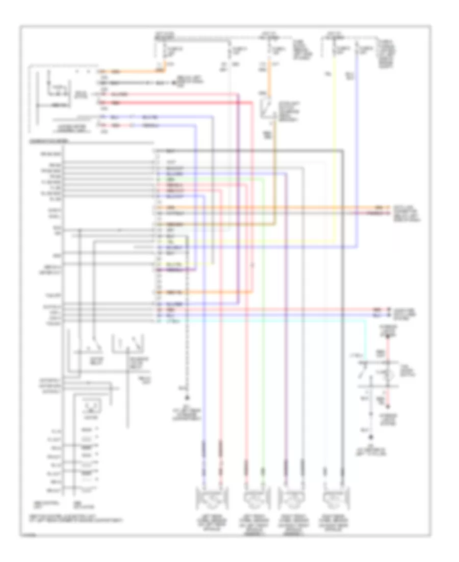
Anti-lock Brakes Wiring Diagram, A/T without Traction Control for Nissan Maxima GXE 2003

List of elements for Anti-lock Brakes Wiring Diagram, A/T without Traction Control for Nissan Maxima GXE 2003:
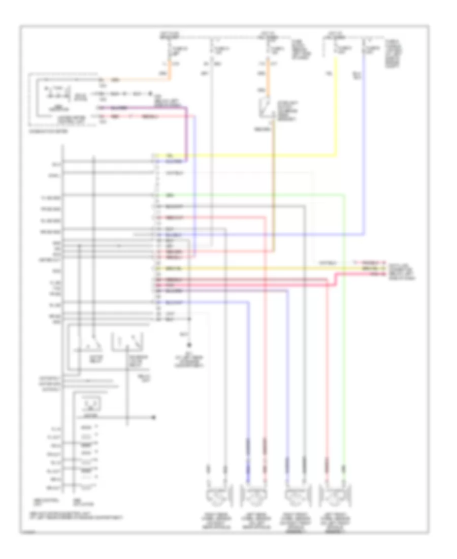
Anti-lock Brakes Wiring Diagram, M/T without Traction Control for Nissan Maxima GXE 2003
List of elements for Anti-lock Brakes Wiring Diagram, M/T without Traction Control for Nissan Maxima GXE 2003:
Anti-lock Brakes Wiring Diagram, with Traction Control for Nissan Maxima GXE 2003
List of elements for Anti-lock Brakes Wiring Diagram, with Traction Control for Nissan Maxima GXE 2003: