ANTI-LOCK BRAKES
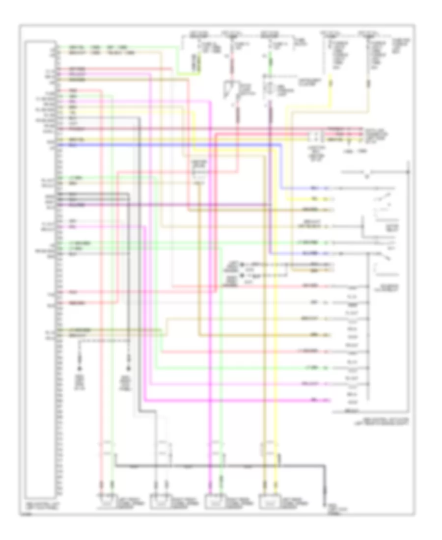
Anti-lock Brake Wiring Diagrams for Nissan Maxima SE 1996
List of elements for Anti-lock Brake Wiring Diagrams for Nissan Maxima SE 1996:
- (1995)
- (1995) (1996)
- (1996)
- (center of i/p)
- (left front fender)
- (right front fender)
- 30a
- Abs control actuator (left rear of engine compt)
- Abs control unit (left kick panel)
- Abs warning lamp
- Bls
- Data link connector (left side
- Diag l
- Fl in
- Fl out
- Fl ss gnd
- Flss
- Fr in
- Fr out
- Fr ss
- Fr ss gnd
- Fuse 10 15a
- Fuse 13 10a
- Fuse 15 7.5a 10a
- Fuse and fusible link box
- Fuse block
- Fusible link c (1995) fusible link i (1996)
- Fusible link e (1995) fusible link g (1996)
- G100
- G101
- G202 (left kick panel)
- G202 (left side of i/p)
- G203 (right kick panel)
- Gnd
- Gnd1
- Gnd2
- Hot at all times
- Hot in on or start
- Instrument cluster
- J/c 13
- Junction box (center of i/p)
- Left front wheel speed sensor
- Left rear wheel speed sensor
- Motor relay
- Nca
- Of i/p)
- Pnk
- Red
- Right front wheel speed sensor
- Right rear wheel speed sensor
- Rl in
- Rl out
- Rl ss
- Rl ss gnd
- Rr in
- Rr out
- Rr ss
- Rr ss gnd
- Rxd
- Sila
- Solenoid valve relay
- Stop lamp switch
- Txd
 English