ANTI-LOCK BRAKES
Anti-lock Brakes Wiring Diagram, with Traction Control for Nissan Murano S 2007

List of elements for Anti-lock Brakes Wiring Diagram, with Traction Control for Nissan Murano S 2007:
- Abs actuator & electric unit (right rear of engine compt)
- Abs ind
- Bat
- Brake fluid level switch (on master cylinder fluid reservoir)
- Brl
- Can-h
- Can-l
- Can1-h
- Can1-l
- Can2-h
- Can2-l
- Clus gnd
- Clus sp
- Combination meter
- Computer data lines system
- Data link connector (below left side of dash)
- Diag k
- Drv 1 gnd
- Drv 1 sig
- Drv 1 ss
- E101
- E13 (left front corner of engine compt)
- E26 (lower right side of engine compt)
- Fl (+)
- Fl (-)
- Fl in sol
- Fl out sol
- Fr (+)
- Fr (-)
- Fr in sol
- Fr out sol
- Fuse & fusible link block (left front of engine compt, near battery)
- Fuse 12 10a
- Fuse 14 10a
- Fuse 19 10a
- Fuse 20 10a
- Fuse 21 10a
- Fuse 82 10a
- Fuse block (j/b) (below left side of dash)
- Fusible link h 30a
- Fusible link j 50a
- Gnd
- Gnd p
- Gnd v
- Hot at all times
- Hot in on or start
- Hsv1
- Hsv2
- Ign
- Illum
- Intelligent power distribution module (engine room) (ipdm e/r) (right front of engine compt, behind headlight)
- Interior lights system
- Left front wheel sensor (on left wheel hub assembly)
- Left rear wheel sensor (on left rear wheel hub assembly)
- Lis
- M14 (behnd left end of dash)
- M25
- M49
- M50
- M78 (behind right end of dash)
- M78 (behnd right end of dash)
- Mot (+)
- Mot (-)
- Mot bat
- Pnk
- Pressure sensor (left rear of engine compt)
- Red
- Right front wheel sensor (on right wheel hub assembly)
- Right rear wheel sensor (on right rear wheel hub assembly)
- Rl (+)
- Rl (-)
- Rl in sol
- Rl out sol
- Rr (-)
- Rr +
- Rr in sol
- Rr out sol
- Slip ind
- Sol bat
- Steering angle sensor (below left side of dash, near steering column)
- Stop lamp switch (above brake pedal, on bracket)
- Unified meter & a/c amplifier (behind lower center of dash)
- Unified meter control unit
- Usv1
- Usv2
- V out
- Vcc
- Vdc off
- Vdc off ind
- Vdc off switch
- Vdc/tcs/abs control unit
- Yaw rate/side/ decel g sensor (below center console)
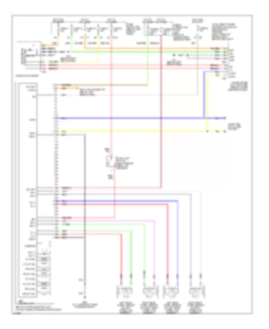
Anti-lock Brakes Wiring Diagram, without Traction Control for Nissan Murano S 2007
List of elements for Anti-lock Brakes Wiring Diagram, without Traction Control for Nissan Murano S 2007:
- Abs actuator & electric unit (at right rear of engine compartment)
- Abs control unit
- Abs ind
- Bat
- Brl
- Can-h
- Can-l
- Combination meter
- Computer data lines system
- Control unit
- Data link connector (below left side of dash)
- Diag k
- E101
- E26 (at lower right side of engine compt)
- Fl (+)
- Fl (-)
- Fl in sol
- Fl out sol
- Fr (+)
- Fr (-)
- Fr in sol
- Fr out sol
- Fuse & fusible link block (left front of engine compt, near battery)
- Fuse 12 10a
- Fuse 14 10a
- Fuse 19 10a
- Fuse 20 10a
- Fuse 21 10a
- Fuse 82 10a
- Fuse block (j/b) (below left side of dash)
- Fusible link g 30a
- Fusible link h 30a
- G sensor
- Gnd
- Gnd p
- Gnd v
- Hot at all times
- Hot in on or start
- Ign
- Intelligent power distribution module (engine room) (ipdm e/r) (right front of engine compt, behind headlight)
- Left front wheel sensor (on left wheel hub assembly)
- Left rear wheel sensor (on left rear wheel hub assembly)
- M14 (behind left end of dash)
- M25
- M49
- M50
- M78 (behind right end of dash)
- Mot (+)
- Mot (-)
- Mot bat
- Pnk
- Red
- Right front wheel sensor (on right wheel hub assembly)
- Right rear wheel sensor (on right rear wheel hub assembly)
- Rl (+)
- Rl (-)
- Rl in sol
- Rl out sol
- Rr (+)
- Rr (-)
- Rr in sol
- Rr out sol
- Sol bat
- Stop lamp switch (above brake pedal, on bracket)
- Unified meter
- Unified meter & a/c amplifier (behind lower center of dash)