ANTI-LOCK BRAKES
Anti-lock Brake Wiring Diagrams for Nissan Pathfinder LE 1998
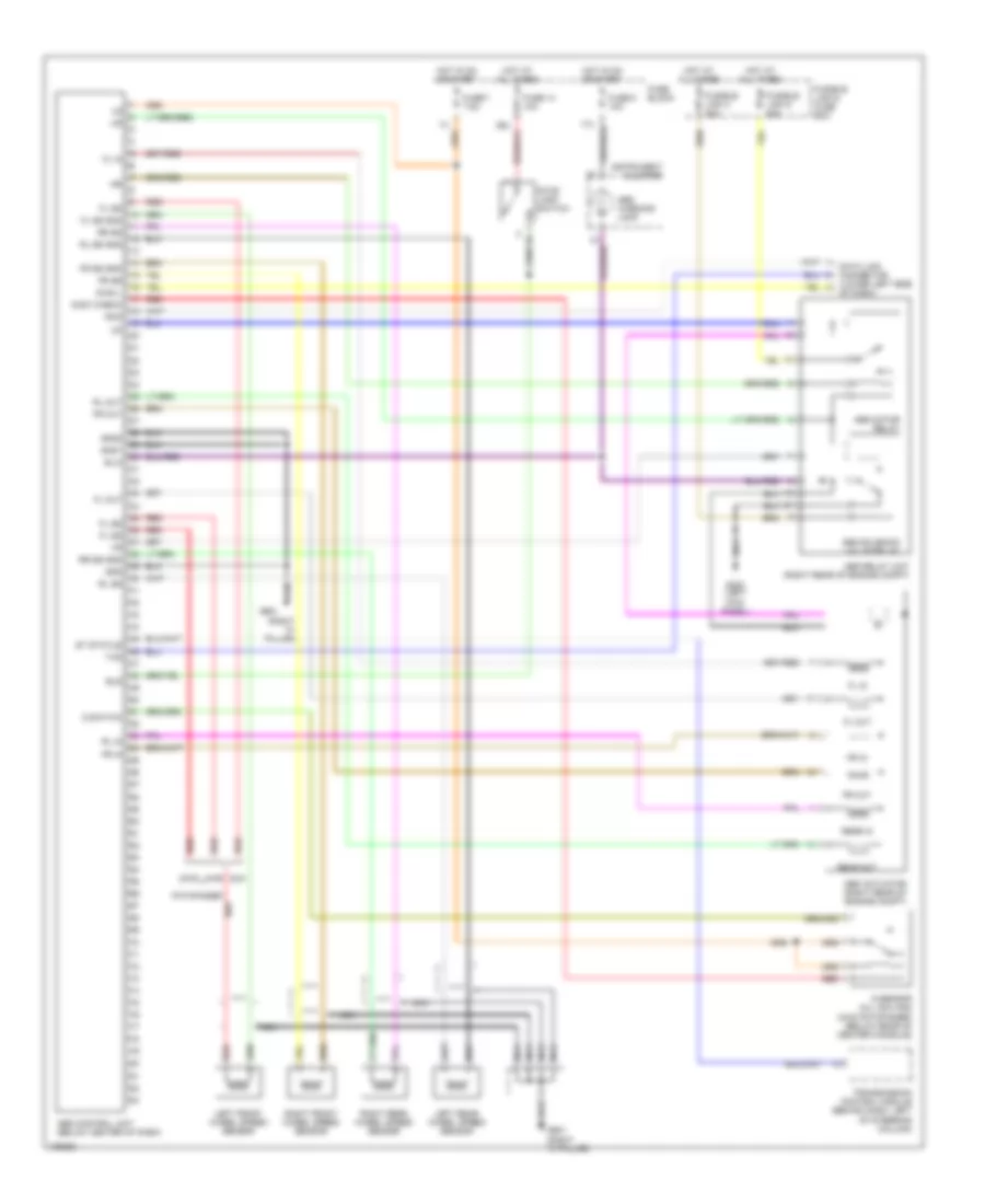
List of elements for Anti-lock Brake Wiring Diagrams for Nissan Pathfinder LE 1998:
- (right "a" pillar)
- 2wd
- 4wd
- Abs actuator (right rear of engine compt)
- Abs control unit (below center of dash)
- Abs motor relay
- Abs relay unit (right rear of engine compt)
- Abs solenoid valve relay
- Abs warning lamp
- Bls
- Data link connector (lower left side
- Diag l
- Fl in
- Fl out
- Fl ss
- Fl ss gnd
- Fr in
- Fr out
- Fr ss
- Fr ss gnd
- Fuse 14 10a
- Fuse 7 7.5a
- Fuse 8 10a
- Fuse block
- Fusible link & fuse box
- Fusible link c 40a
- Fusible link d 40a
- G sensor (all qx4 and (4wd pathfinder) (below rear of center console)
- G switch
- G-sw check
- G200 (left kick panel)
- G901
- G901 (right "a" pillar)
- Gnd
- Gnd1
- Gnd2
- Hot at all times
- Hot in on or start
- Instrument cluster
- Left front wheel speed sensor
- Left rear wheel speed sensor
- Nca
- Of dash)
- Pathfinder
- Qx4
- Rear in
- Rear out
- Red
- Right front wheel speed sensor
- Right rear wheel speed sensor
- Rl in
- Rl out
- Rl ss
- Rl ss gnd
- Rr ss
- Rr ss gnd
- Rxd
- Sila
- St status
- Stop lamp switch
- Transmission control module (behind dash, left of steering column)
- Txd
 English