ANTI-LOCK BRAKES
4.0L
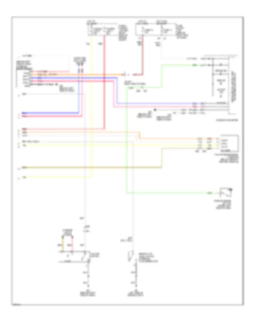
4.0L, Anti-lock Brakes Wiring Diagram (1 of 2) for Nissan Pathfinder LE 2012

List of elements for 4.0L, Anti-lock Brakes Wiring Diagram (1 of 2) for Nissan Pathfinder LE 2012:
- (on left side of engine compt) abs actuator & electric unit (control unit)
- 15c
- 16c
- 17c
- 18c
- 44g
- Abs/tcs/vdc control unit
- Brake level sw
- Can-h
- Can-l
- Can2-h
- Can2-l
- Clus gnd
- Clus sp
- Computer data lines system
- Diag k
- E119
- E126
- E152
- E160
- E26
- E41
- Exterior lights system
- Fl in sol
- Fl out sol
- Fr in sol
- Fr lh pwr
- Fr lh sig
- Fr out sol
- Fr rh pwr
- Fr rh sig
- Fuse 10a
- Fuse block (j/b) (behind right end of dash)
- Gnd p
- Gnd v
- Hot at all times
- Hot in on or start
- Hsv1 (mc1) usv2 (mc2) usv1 (mc1)
- Hsv2 (mc2)
- Ign
- Ipdm e/r (intelligent power distribution module engine room) (right rear of engine compt)
- Kl30 v
- Kl30-p
- Left front wheel sensor (at left front steering knuckle assembly)
- Left rear wheel sensor
- M31
- M91
- Mot (+)
- Mot (-)
- Motor
- Pnk
- Rear wheel sensor assembly (under rear of vehicle)
- Red
- Right front wheel sensor (at right front steering knuckle assembly)
- Right rear wheel sensor
- Rl in sol
- Rl out sol
- Rr in sol
- Rr lh pwr
- Rr lh sig
- Rr out sol
- Rr rh pwr
- Rr rh sig
- Solenoid valves
- Stop lamp sw
- Stop lamp switch (on bracket, above brake pedal)
- Vdc off sw
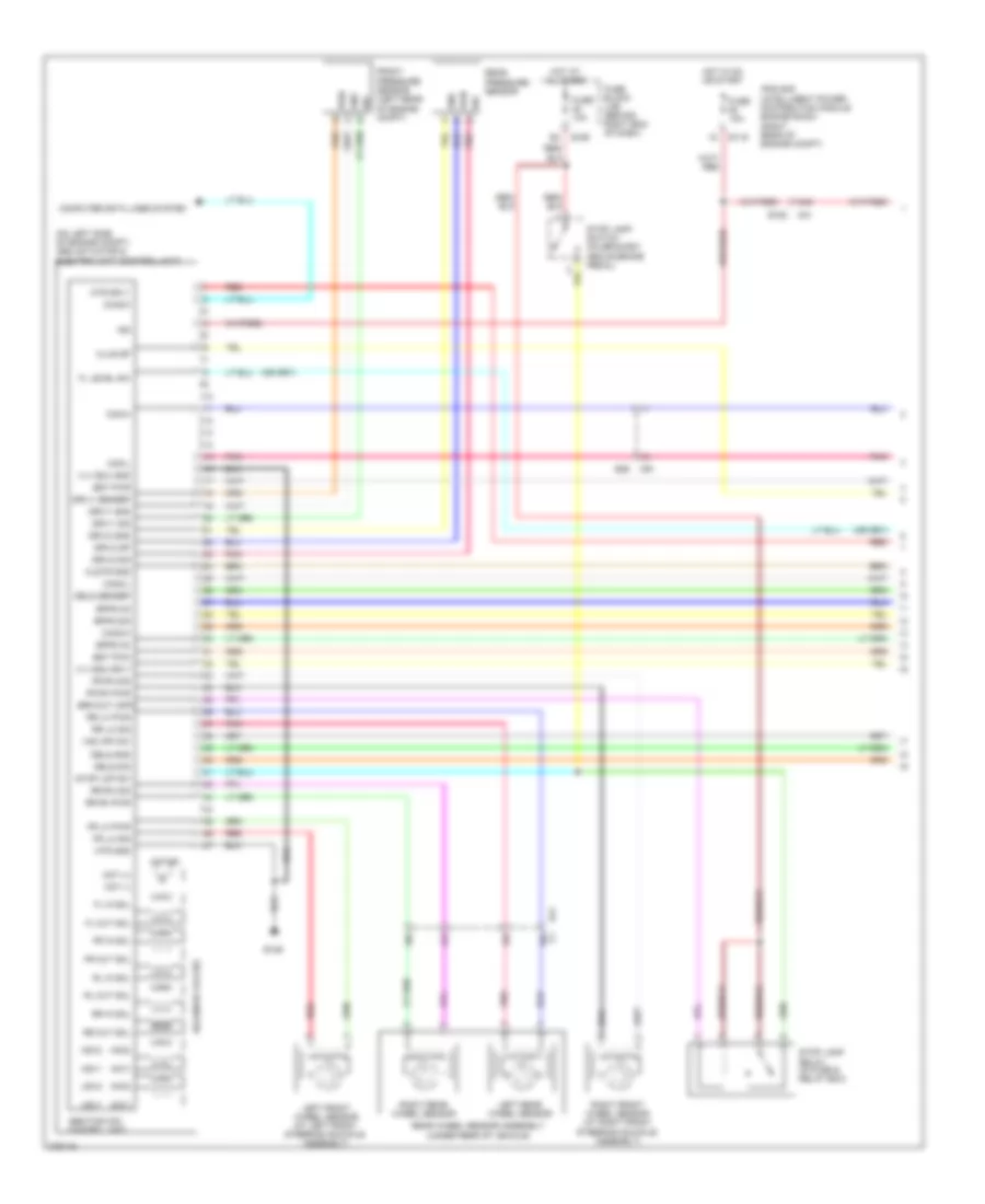
4.0L, Anti-lock Brakes Wiring Diagram (2 of 2) for Nissan Pathfinder LE 2012
List of elements for 4.0L, Anti-lock Brakes Wiring Diagram (2 of 2) for Nissan Pathfinder LE 2012:
- (behind left side of dash)
- Abs ind
- B40
- Batt
- Brake fluid level switch (on brake fluid reservoir)
- Brake ind
- Can-h
- Can-l
- Clu gnd
- Clu p
- Combination meter
- Computer data lines system
- E26
- E34
- E9 (left side of engine compt)
- Fuse & fusible link box (right rear of engine compt)
- Fuse 14 10a
- Fuse 18 10a
- Fuse block (j/b) (behind right end of dash)
- Fusible link l 30a
- Fusible link n 40a
- Gnd
- Hot at all times
- Hot in on or start
- Illum
- Interior lights system
- J/c m01 (right end of dash)
- M57 (behind left side of dash)
- M61 (behind right side of dash)
- M91
- Parking brake switch (under left side of dash)
- Pnk
- Pwr
- Red
- Slip ind
- Steering angle sensor
- Unified meter control unit (w/ information display)
- Vdc off ind
- Vdc off switch
- Yaw rate/side/decel g sensor (below rear of center console)
5.6L
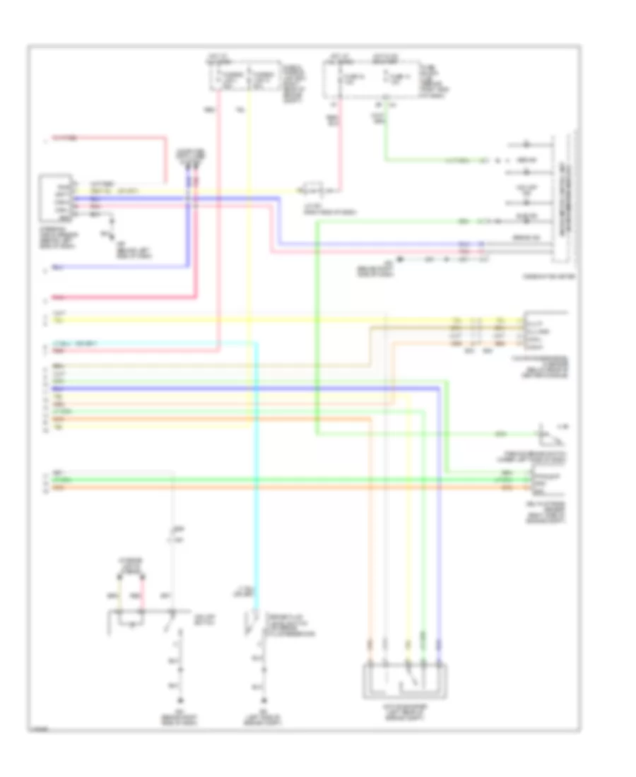
5.6L, Anti-lock Brakes Wiring Diagram (1 of 2) for Nissan Pathfinder LE 2012
List of elements for 5.6L, Anti-lock Brakes Wiring Diagram (1 of 2) for Nissan Pathfinder LE 2012:
- (mc1)
- (mc2)
- (on left side of engine compt) abs actuator & electric unit (control unit)
- 15c
- 17c
- 18c
- 44g
- Abs/tcs/vdc control unit
- Bpfs nc
- Bpfs no
- Bpfs sig
- Brk-out (off)
- Bst pwm
- Bst pwr
- C1 16c
- Can-h
- Can-l
- Can2-h
- Can2-l
- Clstr gnd
- Clus sp
- Computer data lines system
- Dels gnd
- Dels sensep
- Dels sig
- Diag-k
- Driv1 gnd
- Driv1 sensep
- Driv1 sig
- Driv2 gnd
- Driv2 sig
- Driv2 sp
- E119
- E126
- E152
- E160
- E26
- E41
- Fl in sol
- Fl level sw
- Fl out sol
- Fr in sol
- Fr lh pwr
- Fr lh sig
- Fr out sol
- Fr rh pwr
- Fr rh sig
- Front pressure sensor (left rear of engine compt)
- Fuse 10a
- Fuse block (j/b) (behind right end of dash)
- Gnd
- Hot at all times
- Hot in on or start
- Hsv1
- Hsv2
- Ign
- Ipdm e/r (intelligent power distribution module engine room) (right rear of engine compt)
- Left front wheel sensor (at left front steering knuckle assembly)
- Left rear wheel sensor
- M31
- M91
- Mot (+)
- Mot (-)
- Motor
- Mtr gnd
- Mtr sply
- Pnk
- Pwr
- Rear pressure sensor
- Rear wheel sensor assembly (under rear of vehicle)
- Red
- Right front wheel sensor (at right front steering knuckle assembly)
- Right rear wheel sensor
- Rl in sol
- Rl out sol
- Rr in sol
- Rr lh pwr
- Rr lh sig
- Rr out sol
- Rr rh pwr
- Rr rh sig
- Sig
- Solenoid valves
- Stop lamp relay (in fuse & relay box)
- Stop lamp switch (on bracket, above brake pedal)
- Stop lmp sw
- Usv1
- Usv2
- Vdc off sw
- Vlv ecu gnd
- Vlv ecu sply
5.6L, Anti-lock Brakes Wiring Diagram (2 of 2) for Nissan Pathfinder LE 2012
List of elements for 5.6L, Anti-lock Brakes Wiring Diagram (2 of 2) for Nissan Pathfinder LE 2012:
- Abs ind
- Active booster (left rear of engine compt)
- B40
- Batt
- Brake fluid level switch (on brake fluid reservoir)
- Brake ind
- Can-h
- Can-l
- Clu gnd
- Clu p
- Combination meter
- Computer data lines system
- Delta stroke sensor (right side of engine compt)
- E26
- E34
- E9 (left side of engine compt)
- Fuse & fusible link box (right rear of engine compt)
- Fuse 14 10a
- Fuse 18 10a
- Fuse block (j/b) (behind right end of dash)
- Fusible link l 30a
- Fusible link n 40a
- Gnd
- Hot at all times
- Hot in on or start
- Interior lights system
- J/c m01 (right end of dash)
- M57 (behind left side of dash)
- M61 (behind right side of dash)
- M91
- Parking brake switch (under left side of dash)
- Pnk
- Pwr
- Pwr_sup
- Red
- Sig
- Slip ind
- Steering angle sensor (behind left side of dash)
- Unified meter control unit (w/ information display)
- Vdc off ind
- Vdc off switch
- Yaw rate/side/decel g sensor (below rear of center console)