ANTI-LOCK BRAKES
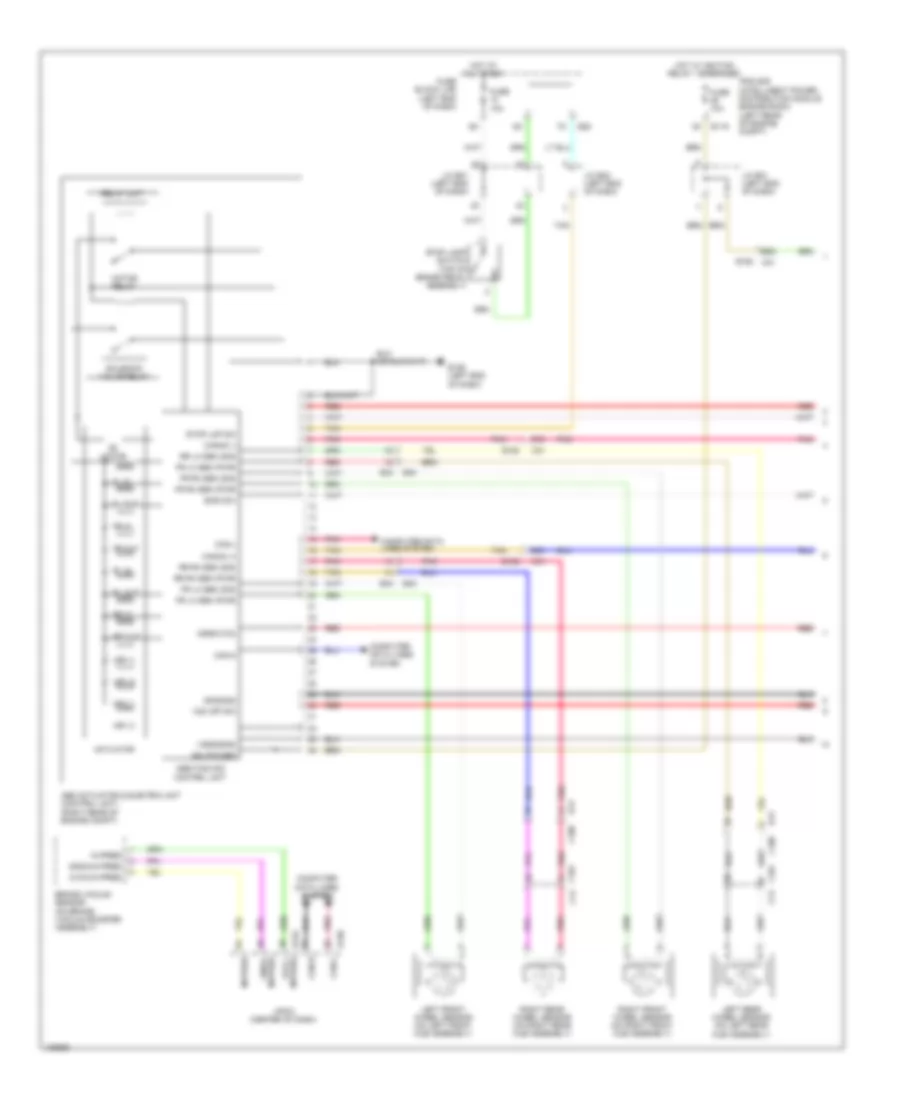
Anti-lock Brakes Wiring Diagram, Except Hybrid (1 of 2) for Nissan Pathfinder S 2014

List of elements for Anti-lock Brakes Wiring Diagram, Except Hybrid (1 of 2) for Nissan Pathfinder S 2014:
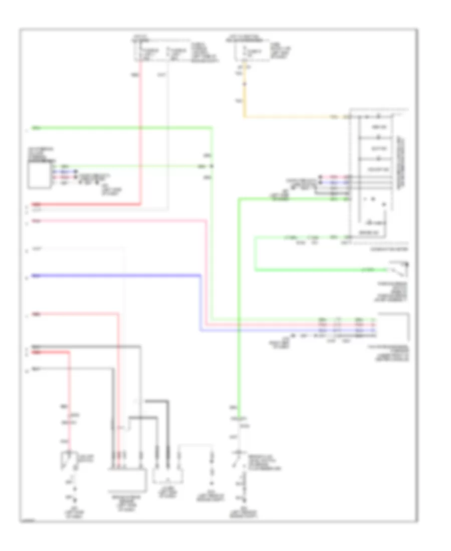
Anti-lock Brakes Wiring Diagram, Except Hybrid (2 of 2) for Nissan Pathfinder S 2014
List of elements for Anti-lock Brakes Wiring Diagram, Except Hybrid (2 of 2) for Nissan Pathfinder S 2014:
Anti-lock Brakes Wiring Diagram, Hybrid (1 of 2) for Nissan Pathfinder S 2014
List of elements for Anti-lock Brakes Wiring Diagram, Hybrid (1 of 2) for Nissan Pathfinder S 2014:
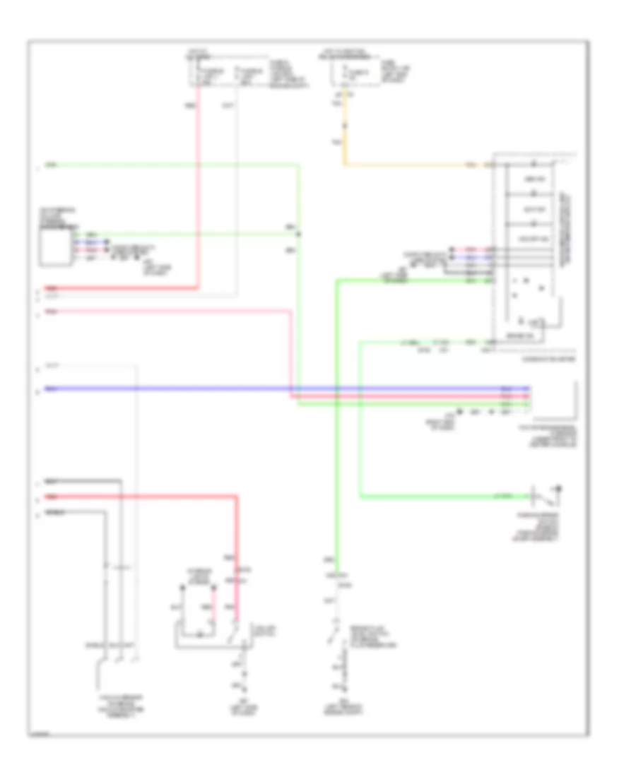
Anti-lock Brakes Wiring Diagram, Hybrid (2 of 2) for Nissan Pathfinder S 2014
List of elements for Anti-lock Brakes Wiring Diagram, Hybrid (2 of 2) for Nissan Pathfinder S 2014: