ANTI-LOCK BRAKES
Anti-lock Brake Wiring Diagrams for Nissan Quest GLE 1999
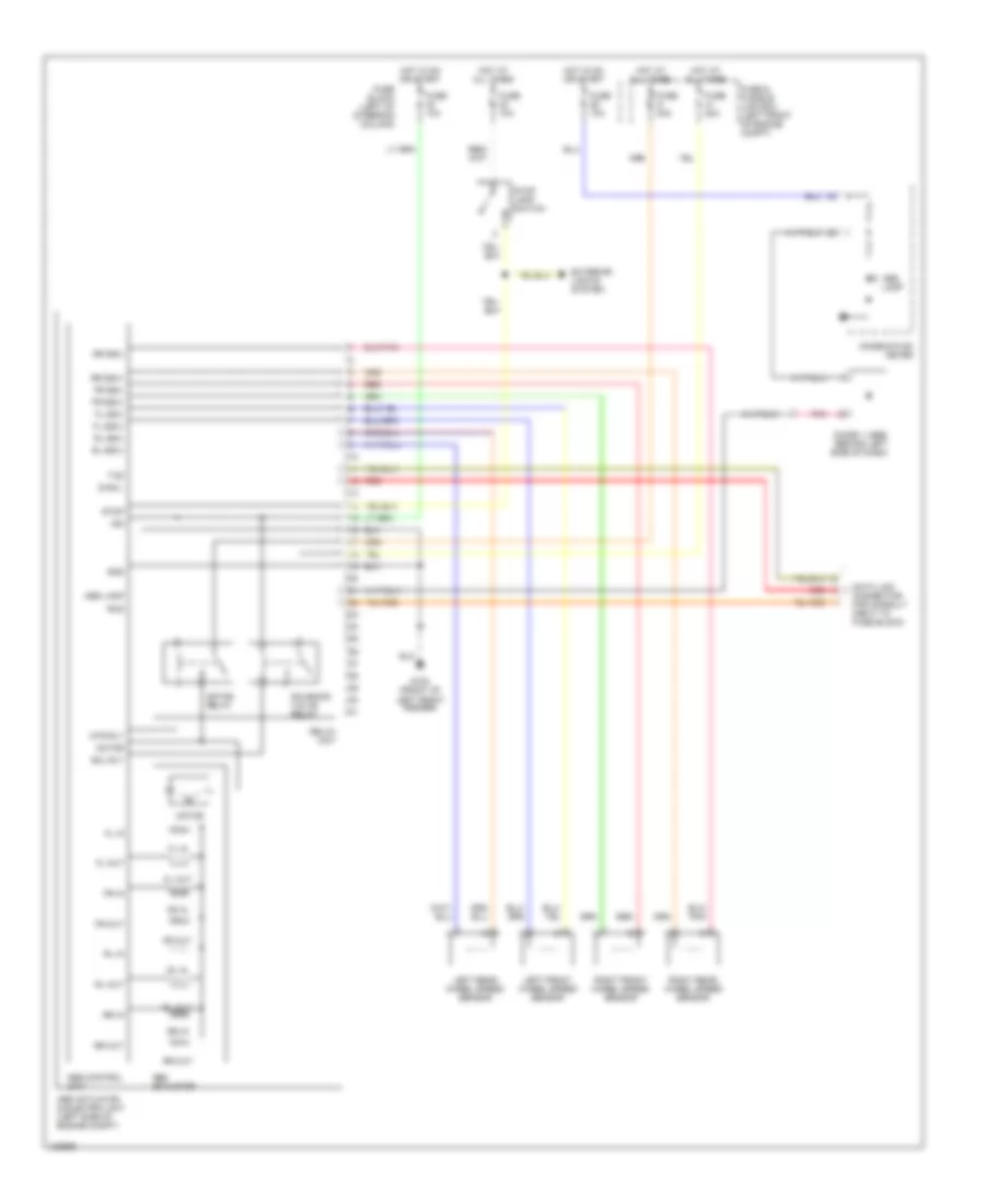
List of elements for Anti-lock Brake Wiring Diagrams for Nissan Quest GLE 1999:
- Abs actuator
- Abs actuator & electric unit (left side of engine compt)
- Abs control unit
- Abs lamp
- Combination meter
- Data link connector for consult (next to fuse block)
- Diag l
- Diode 1 (abs) (behind left side of dash)
- Exterior lights system
- Fl in
- Fl out
- Fl ss(+)
- Fl ss(-)
- Fr in
- Fr out
- Fr ss(+)
- Fr ss(-)
- Fuse & fusible link box (left front of engine compt)
- Fuse 10a
- Fuse 20a
- Fuse block (left of steering column)
- Fuse g 30a
- G100 (front of left front fender)
- Gnd
- Hot at all times
- Hot in on or start
- Ign
- Left front wheel speed sensor
- Left rear wheel speed sensor
- Motor
- Motor relay
- Mtr rly
- Pnk
- Red
- Relay unit
- Right front wheel speed sensor
- Right rear wheel speed sensor
- Rl in
- Rl out
- Rl ss(+)
- Rl ss(-)
- Rr in
- Rr out
- Rr ss(+)
- Rr ss(-)
- Rxd
- Sol rly
- Solenoid valve relay
- Stop
- Stop lamp switch
- Txd
 English