ANTI-LOCK BRAKES
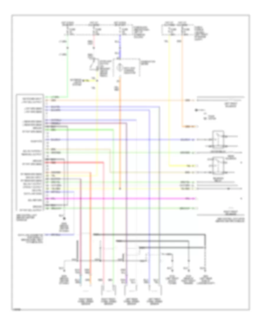
Anti-lock Brake Wiring Diagrams for Nissan Quest XE 1998
List of elements for Anti-lock Brake Wiring Diagrams for Nissan Quest XE 1998:
- 87a
- Abs control actuator (behind center console)
- Abs control unit (behind center console)
- Anti-lock warning indicator
- Boo sw input
- Combination meter
- Data link conn
- Data link connector (for consult) (behind dash, next to fuse block)
- Exterior lights system
- Fuse & fusible link box (left front of engine compt)
- Fuse 10a
- Fuse 15a
- Fuse 20a
- Fuse b 30a
- Fuse block (behind dash, left of steering column)
- G102 (left front shock tower)
- G105 (rear of right front fender)
- G206 (behind center of dash)
- G404 (left rear side of luggage compt)
- Ground
- Hot at all times
- Hot in run or start
- Ign power input
- Ind ctrl
- L fnt sol output
- L fnt spd sens
- L rear spd sens
- Left front solenoid
- Left front wheel speed sensor
- Left rear wheel speed sensor
- Motor relay
- Mtr rly output
- Nca
- Pump motor
- Pump mtr
- Rear sol output
- Rear solenoid
- Red
- Right front solenoid
- Right front wheel speed sensor
- Right rear wheel speed sensor
- Rt fnt sol output
- Rt fnt spd sens
- Rt rear spd sens
- Sol return
- Sol rly output
- Sol rly/mtr rly
- Solenoid relay
- Stoplamp switch (on bracket, above brake pedal)
 Русский