ANTI-LOCK BRAKES
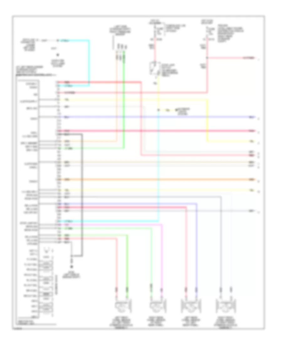
Anti-lock Brakes Wiring Diagram, with Traction Control & Stability Assist with Hill Assist (1 of 2) for Nissan Xterra S 2006

List of elements for Anti-lock Brakes Wiring Diagram, with Traction Control & Stability Assist with Hill Assist (1 of 2) for Nissan Xterra S 2006:
- (at left rear corner of engine compt) abs actuator & electric unit (control unit)
- (frontier: at left rear corner of engine compt) (xterra: left side of engine compt) rear pressure sensor
- (frontier: left rear of engine compt) (xterra: left side of engine compt) front pressure sensor
- Abs/tcs/vdc control unit
- Bpfs nc
- Bpfs no
- Bpfs sig
- Br fl sw
- Bst pwm
- Bst pwr
- Can1-h
- Can1-l
- Can2-h
- Can2-l
- Clstr gnd
- Computer data lines system
- Data link connector (under left side of dash)
- Diag-k
- Driv1 gnd
- Driv1 sensep
- Driv1 sig
- Driv2 gnd
- Driv2 sig
- Driv2 sp
- E119
- E126 (left side of engine compt)
- E160
- Exterior lights system
- Fl in sol
- Fl out sol
- Fr in sol
- Fr lh pwr
- Fr lh sig
- Fr out sol
- Fr rh pwr
- Fr rh sig
- Fuse 10a
- Fuse block (j/b) (xterra: right side of dash) (frontier: under right side of dash)
- Gnd
- Hdc sw
- Hot at all times
- Hot in on or start
- Hsv1
- Hsv2
- Ign
- Ipdm e/r (intelligent power distribution module engine room) (right rear of engine compt)
- Lamp sw
- Left front wheel sensor (on left front wheel knuckle assembly)
- Left rear wheel sensor (at left wheel well)
- Mot (+)
- Mot (-)
- Mtr gnd
- Mtr sply
- Pnk
- Pwr
- Red
- Right front wheel sensor (on right front wheel knuckle assembly)
- Right rear wheel sensor (at right rear wheelwell)
- Rl in sol
- Rl out sol
- Rr in sol
- Rr lh pwr
- Rr lh sig
- Rr out sol
- Rr rh pwr
- Rr rh sig
- Sig
- Solenoid valve
- Stop lamp relay (in fuse & relay box)
- Stop lamp switch (on bracket, above brake pedal)
- Stop sw
- Usv1
- Usv2
- Vdc off sw
- Vlv ecu gnd
- Vlv ecu sply
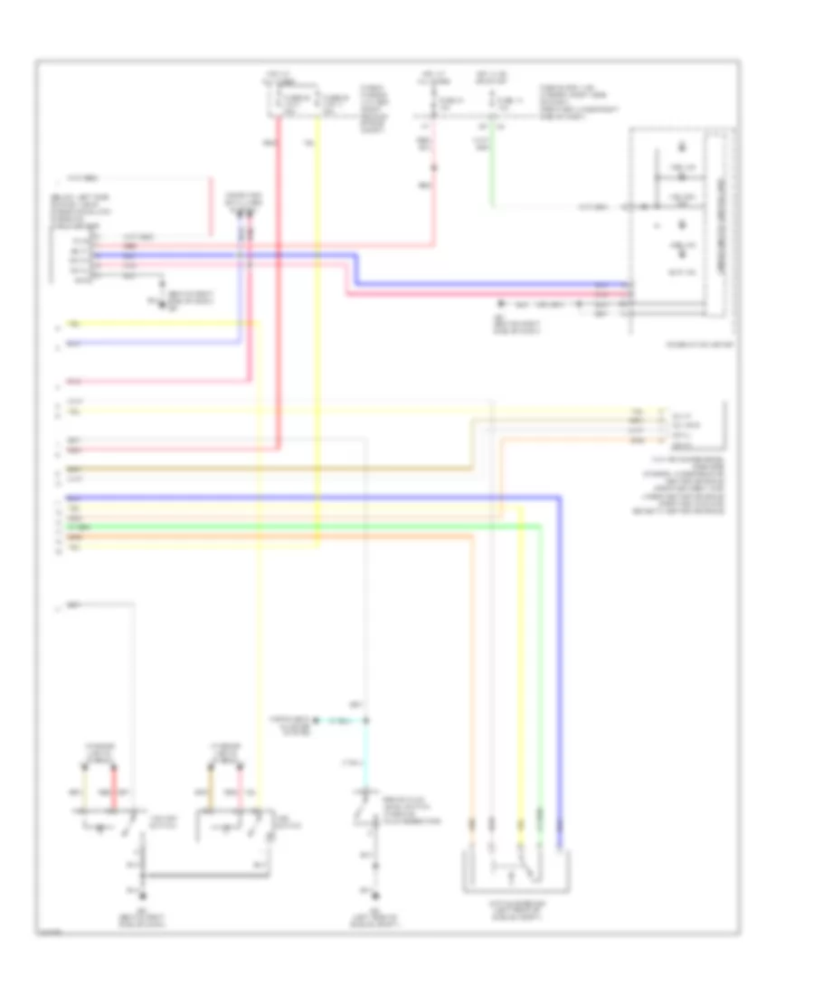
Anti-lock Brakes Wiring Diagram, with Traction Control & Stability Assist with Hill Assist (2 of 2) for Nissan Xterra S 2006
List of elements for Anti-lock Brakes Wiring Diagram, with Traction Control & Stability Assist with Hill Assist (2 of 2) for Nissan Xterra S 2006:
- (behind right side of dash) m61
- (below left side of dash, near steering column) steering angle sensor
- Abs ind
- Active booster (left rear of engine compt)
- Batt
- Brake fluid level switch (in brake fluid reservoir)
- Can-h
- Can-l
- Clu gnd
- Clu p
- Combination meter
- Computer data lines system
- E9 (left side of engine compt)
- Fuse & fusible link box (right rear of engine compt)
- Fuse 14 10a
- Fuse 21 10a
- Fuse block (j/b) (xterra: right side of dash) (frontier: under right side of dash)
- Fusible link i 30a
- Fusible link n 40a
- Gnd
- Hdc ind
- Hdc switch
- Hot at all times
- Hot in on or start
- Instrument cluster system
- Interior lights system
- M61 (behind right side of dash)
- Pnk
- Pwr
- Red
- Slip ind
- Unified meter control unit
- Vdc off ind
- Vdc off switch
- Yaw rate/side/decel g sensor (xterra: under rear of center console) (frontier crew cab: under center console) (frontier king cab: beneath center console)
Anti-lock Brakes Wiring Diagram, with Traction Control & Stability Assist, without Hill Assist (1 of 2) for Nissan Xterra S 2006
List of elements for Anti-lock Brakes Wiring Diagram, with Traction Control & Stability Assist, without Hill Assist (1 of 2) for Nissan Xterra S 2006:
- ( left side of engine compt)
- (at left rear corner of engine compt) abs actuator & electric unit (control unit)
- Abs/tcs/vdc control unit
- Br fl sw
- Can-h
- Can-l
- Can2-h
- Can2-l
- Clstr gnd
- Computer data lines system
- Data link connector (under left side of dash)
- Diag-k
- Driv1 gnd
- Driv1 sensep
- Driv1 sig
- E119
- E126 (left side of engine compt)
- E160
- Exterior lights system
- Fl in sol
- Fl out sol
- Fr in sol
- Fr lh pwr
- Fr lh sig
- Fr out sol
- Fr rh pwr
- Fr rh sig
- Front pressure sensor
- Fuse 10a
- Fuse block (j/b) (right side of dash)
- Gnd
- Hot at all times
- Hot in on or start
- Hsv1
- Hsv2
- Ign
- Ipdm e/r (intelligent power distribution module engine room) (right rear of engine compt)
- Left front wheel sensor (at left front steering knuckle assembly)
- Left rear wheel sensor (at left rear wheel)
- Mot (+)
- Mot (-)
- Mtr gnd
- Mtr sply
- Pnk
- Pwr
- Red
- Right front wheel sensor (at right front steering knuckle assembly)
- Right rear wheel sensor (at right rear wheel)
- Rl in sol
- Rl out sol
- Rr in sol
- Rr lh pwr
- Rr lh sig
- Rr out sol
- Rr rh pwr
- Rr rh sig
- Sig
- Solenoid valve
- Stop lamp sw
- Stop lamp switch (on bracket, above brake pedal)
- Usv1
- Usv2
- Vdc off sw
- Vlv ecu gnd
- Vlv ecu sply
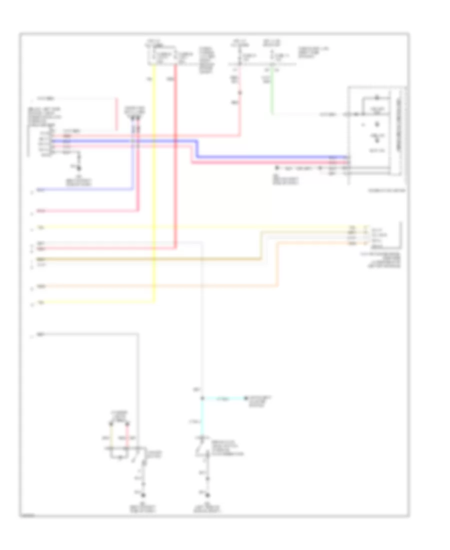
Anti-lock Brakes Wiring Diagram, with Traction Control & Stability Assist, without Hill Assist (2 of 2) for Nissan Xterra S 2006
List of elements for Anti-lock Brakes Wiring Diagram, with Traction Control & Stability Assist, without Hill Assist (2 of 2) for Nissan Xterra S 2006:
- (below left side of dash, near steering column) steering angle sensor
- Abs ind
- Batt
- Brake fluid level switch (in brake fluid reservoir)
- Can-h
- Can-l
- Clu gnd
- Clu p
- Combination meter
- Computer data lines system
- E9 (left side of engine compt)
- Fuse & fusible link box (right rear of engine compt)
- Fuse 14 10a
- Fuse 21 10a
- Fuse block (j/b) (right side of dash)
- Fusible link i 30a
- Fusible link n 40a
- Gnd
- Hot at all times
- Hot in on or start
- Instrument cluster system
- Interior lights system
- M61 (behind right side of dash)
- Pnk
- Pwr
- Red
- Slip ind
- Unified meter control unit
- Vdc off ind
- Vdc off switch
- Yaw rate/side/decel g sensor (under rear of center console)