ANTI-LOCK BRAKES
Anti-lock Brakes Wiring Diagram (1 of 2) for Pontiac G6 GXP 2008

List of elements for Anti-lock Brakes Wiring Diagram (1 of 2) for Pontiac G6 GXP 2008:
- (left front of engine compt, on left rear side of core support, between g101 & g104) g109
- 5v ref
- Abs fuse 15 10a
- Abs fuse 24 60a
- B+ pump motor control
- Bat
- Batt abs fuse 55 30a
- Brake pressure modulator valve (bpmv)
- Computer data lines system
- Electronic brake control module (ebcm) (left side of engine compt, mounted to back side of strut tower, part of brake pressure modulator valve (bpmv))
- G109 (left front of engine compt, on left rear side of core support, between g101 & g104)
- Gmlan serial data (+)
- Gmlan serial data (-)
- Gnd
- Hot at all times
- Hot w/ run/crank relay energized
- Ign 1 voltage
- Lateral accelerometer sig
- Left front wheel speed sensor (wss) (in left front wheel hub)
- Left rear wheel speed sensor (wss) (in left rear wheel hub)
- Lf wheel sens sply voltage
- Lf wheel spd sens sig
- Longitudinal accelerometer sig
- Low ref
- Lr wheel sens sply voltage
- Lr wheel spd sens sig
- Nca
- Pnk
- Pump motor
- Rf wheel sens sply voltage
- Rf wheel spd sens sig
- Right front wheel speed sensor (wss) (in right front wheel hub)
- Right rear wheel speed sensor (wss) (in right rear wheel hub)
- Rr wheel sens sply voltage
- Rr wheel spd sens sig
- Steering wheel speed/ position sensor (w/ automatic electronic controlled ride & handling) (under left side of dash)
- Strng wheel pos sig a
- Strng wheel pos sig b
- Tan
- Underhood fuse block (in left side of engine compt)
- W/ automatic electronic controlled ride & handling
- Yaw rate diagnostic
- Yaw rate sens sig
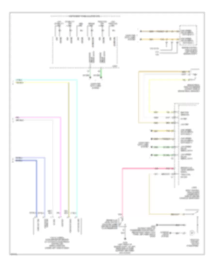
Anti-lock Brakes Wiring Diagram (2 of 2) for Pontiac G6 GXP 2008
List of elements for Anti-lock Brakes Wiring Diagram (2 of 2) for Pontiac G6 GXP 2008:
- (bcm/ebcm)
- (ebcm)
- (ecm/pcm)
- (if equipped)
- 2.4l
- 3.5l & 3.9l
- 3.6l
- 5v ref
- Abs ind
- Body control module (bcm) (under right side of center console, near dash)
- Brake fluid level sensor signal
- Brake fluid level switch (mounted under center of brake fluid reservoir)
- Brake ind
- Brake pedal position sensor (in right side of brake pedal bracket)
- Brk pos sens sig
- Computer data lines system
- Engine control module (ecm) (left side of engine compt)
- G109 (left front of engine compt, on left rear side of core support, between g101 & g104)
- G305 (on right front of passenger compartment, behind right front kick panel, between g304 & door)
- Gmlan serial data bus (+)
- Gmlan serial data bus (-)
- High speed
- High speed gmlan serial data bus (+)
- High speed gmlan serial data bus (-)
- Ign
- Instrument panel cluster (ipc)
- Interior lights system
- Lat accel sig
- Logic
- Long acc sig
- Low ref
- Low speed
- Low speed gmlan
- Low speed gmlan serial data
- Low stability ind
- Low traction ind
- Pnk
- Sens sig yaw rate
- Serial data
- Serial data gmlan
- Stability off ind
- Sw sig
- Tan
- Trac ctrl
- Traction control switch
- Traction off ind
- Yaw & lateral accelerometer sensor (w/ automatic electronic controlled ride & handling) (under left side of dash)
- Yaw rate diag