ANTI-LOCK BRAKES
Anti-lock Brakes Wiring Diagram (1 of 2) for Pontiac G8 GXP 2009

List of elements for Anti-lock Brakes Wiring Diagram (1 of 2) for Pontiac G8 GXP 2009:
- (left rear of engine compt) g102
- Abs mtr fuse fu3 40a
- Abs vlv fuse 5 25a
- Batt pos volt
- Brake pressure modulator valve (bpmv)
- Combin veh inertial sens sig
- Comm enable rly sply volt
- Comm rly sply volt
- Computer data lines system
- Data bus (+)
- Data bus (-)
- Data bus+
- Data bus-
- Electronic brake control module (ebcm) (right rear of engine compt)
- Gnd
- Hot at all times
- J112
- J212 (in instrument panel harness)
- Lf wheel spd sens sig
- Lf wheel spd sens sply volt
- Low ref
- Lr wheel spd sens sig
- Lr wheel spd sens sply volt
- Pump motor
- Rf wheel spd sens sig
- Rf wheel spd sens sply volt
- Rr wheel spd sens sig
- Rr wheel spd sens sply volt
- Steering angle sensor (in steering column)
- Steering wheel pos sens
- Steering wheel position sens
- Underhood fuse block (mounted to right front strut tower)
- Yaw rate & lateral acceleration sensor (under center console)
- Yaw rate sens test ctrl
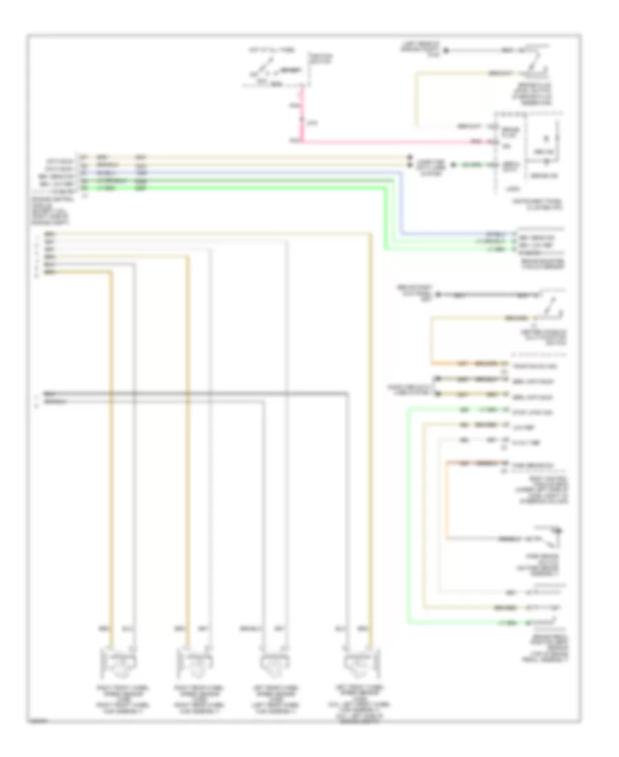
Anti-lock Brakes Wiring Diagram (2 of 2) for Pontiac G8 GXP 2009
List of elements for Anti-lock Brakes Wiring Diagram (2 of 2) for Pontiac G8 GXP 2009:
- (behind right kick panel) g201
- (in brake fluid reservoir)
- (left rear of engine compt) g102
- 5 volts
- 5-volt ref
- Abs ind
- Acc
- Bbv low ref
- Bbv sens sig
- Body control module (bcm) (under left side of dash, right of steering column)
- Brake booster vacuum sensor
- Brake fluid
- Brake fluid level switch
- Brake ind
- Brake pedal position (bpp) sensor (top of brake pedal assembly)
- Center console multi-function switch
- Computer data lines system
- Data bus+
- Data bus-
- Engine control module (except 3.6l) (right side of engine compt)
- Hot at all times
- Ign
- Ignition switch
- Instrument panel cluster (ipc)
- J215
- Left front wheel speed sensor (wss) (3.6l: left front wheel hub assembly) (6.0l: left side of engine compt)
- Left rear wheel speed sensor (wss) (left rear wheel hub assembly)
- Logic
- Low ref
- Off
- Park brake sw
- Park brake switch (on park brake assembly)
- Pnk
- Right front wheel speed sensor (wss) (right front wheel hub assembly)
- Right rear wheel speed sensor (wss) (right rear wheel hub assembly)
- Run
- Serial data
- Serl data bus+
- Serl data bus-
- Start
- Stop lp sw sig
- Traction sw sig