ANTI-LOCK BRAKES
Anti-lock Brakes Wiring Diagram for Pontiac Vibe 2003
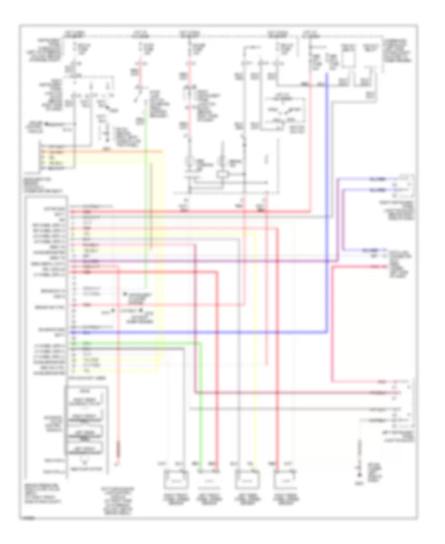
List of elements for Anti-lock Brakes Wiring Diagram for Pontiac Vibe 2003:
- (on right inner fender)
- (pin 32-40 not used)
- Abs ind ctrl
- Abs no 1 fuse 30a
- Abs no 2 fuse 40a
- Abs pump motor
- Abs warning ind
- Acc
- Accelerometer
- Batt
- Brake ind
- Brake ind ctrl
- Brake pressure modulator valve (bpmv) (at right front side of eng compt)
- Brake sw in
- C11
- C12
- Cruise control module
- Data link connector (dlc) obd2 (under left side of dash)
- Daytime running lamp control module (at right side of steering column, above brake pedal)
- Deceleration sensor (awd only) (under driver seat)
- Drl module
- Ecu-ig fuse 10a
- Fan no 1 relay
- Fan no 2 relay
- G102
- G200
- G201
- Gauge fuse 10a
- Hot at all times
- Hot in run or start
- Ign
- Ignition switch
- Instrument cluster system
- Instrument panel fuse block (left of steering column, behind storage compt)
- Left front solenoid valve
- Left front wheel speed sensor
- Left instrument panel junction block
- Left rear solenoid valve
- Left rear wheel speed sensor
- Lf wheel spd hi
- Lf wheel spd lo
- Lr wheel spd hi
- Lr wheel spd lo
- Motor gnd
- Obd2 serial data
- Obd2 ts
- Off
- Pmp mtr hi
- Pmp mtr lo
- Pnk
- Red
- Right front solenoid valve
- Right front wheel speed sensor
- Right instrument panel junction block (behind right side of dash)
- Right rear solenoid valve
- Right rear wheel speed sensor
- Rr wheel spd hi
- Rr wheel spd l0
- Run
- S101
- S115
- S222
- Solenoid gnd
- Solenoid valve control signals
- Sp 200 (under left side of dash)
- Sp 201 (behind right body hinge pillar trim panel)
- Start
- Stop fuse 15a
- Stop lamp switch (on brake pedal support bracket)
- Underhood fuse block (left side of eng compt, mounted to inner fender)
- Vss in
 English