ANTI-LOCK BRAKES
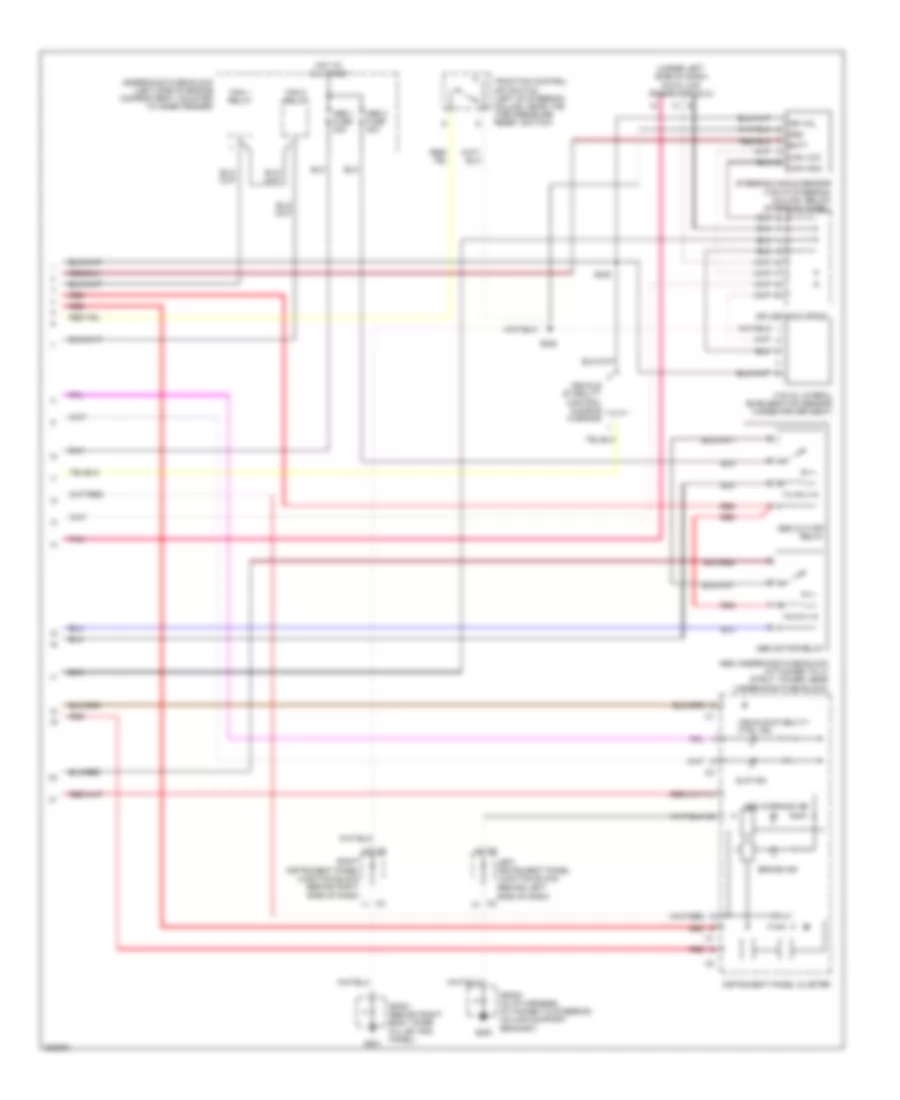
Anti-lock Brakes Wiring Diagram, with VSC (1 of 2) for Pontiac Vibe GT 2006

List of elements for Anti-lock Brakes Wiring Diagram, with VSC (1 of 2) for Pontiac Vibe GT 2006:
- (on right inner fender) g102
- Abs cut off rly
- Abs cut-off relay
- Abs ind ctrl
- Abs motor relay
- Abs motor rly out
- Abs pump motor
- Acc
- Batt
- Brake pressure modulator valve (bpmv) (at right front side of engine compartment)
- Brake sw in
- Brk ind ctrl
- C11
- C12
- Can high
- Can low
- Computer data lines system
- Cruise control system
- Daytime running lamps (drl) control module (at right side of steering column, above brake pedal)
- Drl module
- Ecu-b fuse 10a
- Ecu-ig fuse 10a
- Efi sig high
- Efi sig low
- Engine rpm sig
- Gauge fuse 10a
- Hot at all times
- Hot in run or start
- Ign on vol
- Ignition switch
- Instrument panel fuse block (left of steering column, behind storage compartment)
- Left front solenoid valve
- Left front wheel speed sensor (at front steering knuckle assembly)
- Left rear solenoid valve
- Left rear wheel speed sensor (at rear wheel hub assembly)
- Lf whl spd sig hi
- Lf whl spd sig lo
- Lock
- Lr whl spd sig hi
- Lr whl spd sig lo
- Motor gnd
- Obd2 serial data
- Pcm traction ctrl
- Pmp mtr hi
- Pmp mtr lo
- Pnk
- Pnp sw park sig
- Powertrain control module (pcm) (behind right side of dash)
- Red
- Rf whl spd sig hi
- Rf whl spd sig lo
- Right front solenoid valve
- Right front wheel speed sensor (at front steering knuckle assembly)
- Right instrument panel junction block (behind right side of dash)
- Right rear solenoid valve
- Right rear wheel speed sensor (at rear wheel hub assembly)
- Rr whl spd sig hi
- Rr whl spd sig lo
- Run
- S101
- S121
- S229
- S237
- Serial data
- Sir serial data
- Slip ind ctrl
- Solenoid gnd
- Solenoid valve control signals
- Start
- Stop fuse 15a
- Stop lamp switch (behind left side of dash, on brake pedal support bracket)
- Tire pressure
- Tire pressure sw
- Traction ctrl gnd
- Traction ctrl high
- Transmissions system
- Vehicle ctrl ind
- Vss in
- Warning system
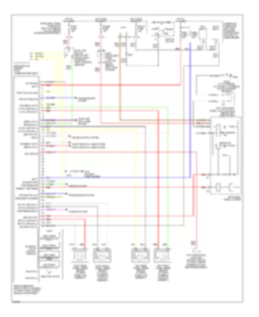
Anti-lock Brakes Wiring Diagram, with VSC (2 of 2) for Pontiac Vibe GT 2006
List of elements for Anti-lock Brakes Wiring Diagram, with VSC (2 of 2) for Pontiac Vibe GT 2006:
- (behind left side of dash)
- (under left side of dash) data link connector (dlc)
- Abs 1 fuse 30a
- Abs 2 fuse 40a
- Abs cut-off relay
- Abs motor relay
- Abs underhood fuse block (attached to lf strut tower, near underhood fuse block)
- Abs warning ind
- Batt
- Brake ind
- Can high
- Can low
- Fan 1 relay
- Fan 2 relay
- G200
- G201
- Gnd
- Hot at all times
- Ign vol
- Instrument panel cluster
- Left instrument panel junction block
- Pnk
- Red
- Right instrument panel junction block (behind right
- S228
- S230
- Side of dash)
- Slip ind
- Sp200 (in i/p harness, attached to steering column support bracket)
- Sp201 (behind right body hinge pillar trim panel)
- Splice pack sp202
- Steering angle sensor (top of steering column, below steering wheel)
- Traction control off switch (left of steering column, near the tire pressure reset switch)
- Underhood fuse block (left side of engine compartment, mounted to inner fender)
- Vehicle stability control audible warning
- Vehicle stability ctrl ind
- Yaw & lateral acceleration sensor (under driver seat)
Anti-lock Brakes Wiring Diagram, without VSC for Pontiac Vibe GT 2006
List of elements for Anti-lock Brakes Wiring Diagram, without VSC for Pontiac Vibe GT 2006:
- Abs 1 fuse 30a
- Abs 2 fuse 40a
- Abs ind ctrl
- Abs pump motor
- Abs warning
- Acc
- Ambient temp sens
- Batt
- Brake ind
- Brake pressure modulator valve (bpmv) (at right front side of engine compartment)
- Brake sw in
- Brk ind ctrl
- C11
- C12
- Computer data lines system
- Cruise control system
- Daytime running lamps (drl) control module (at right side of steering column, above brake pedal)
- Deceleration sens
- Deceleration sensor (awd) (under driver's seat)
- Drl module
- Ecu-ig fuse 10a
- Fan 1 relay
- Fan 2 relay
- G102 (on right inner fender)
- G200
- Gauge fuse 10a
- Hot at all times
- Hot in run or start
- Ign positive vol
- Ignition switch
- Ind
- Instrument panel cluster
- Instrument panel fuse block (left of steering column, behind storage compartment)
- Left front solenoid valve
- Left front wheel speed sensor (at front steering knuckle assembly)
- Left instrument panel junction block (behind left side of dash)
- Left rear solenoid valve
- Left rear wheel speed sensor (at rear wheel hub assembly)
- Lf whl spd sig hi
- Lf whl spd sig lo
- Lock
- Lr whl spd sig hi
- Lr whl spd sig lo
- Motor gnd
- Pmp mtr hi
- Pmp mtr lo
- Pnp sw park sig
- Prk neutral sw
- Red
- Rf whl spd sig hi
- Rf whl spd sig lo
- Right front solenoid valve
- Right front wheel speed sensor (at front steering knuckle assembly)
- Right instrument panel junction block (behind right side of dash)
- Right rear solenoid valve
- Right rear wheel speed sensor (at rear wheel hub assembly)
- Rr whl spd sig hi
- Rr whl spd sig lo
- Run
- S101
- S237
- Serial data
- Sir serial data
- Solenoid gnd
- Solenoid valve control signals
- Sp200 (in i/p harness, attached to steering column support bracket)
- Start
- Stop fuse 15a
- Stop lamp switch (behind left side of dash, on brake pedal support bracket)
- Tire pressure
- Tire pressure sw
- Traction ctrl gnd
- Transmissions system
- Underhood fuse block (left side of engine compartment, mounted to inner fender)
- Vss in
- Warning system