ANTI-LOCK BRAKES
Anti-lock Brakes Wiring Diagram for Porsche Boxster Spyder 2012
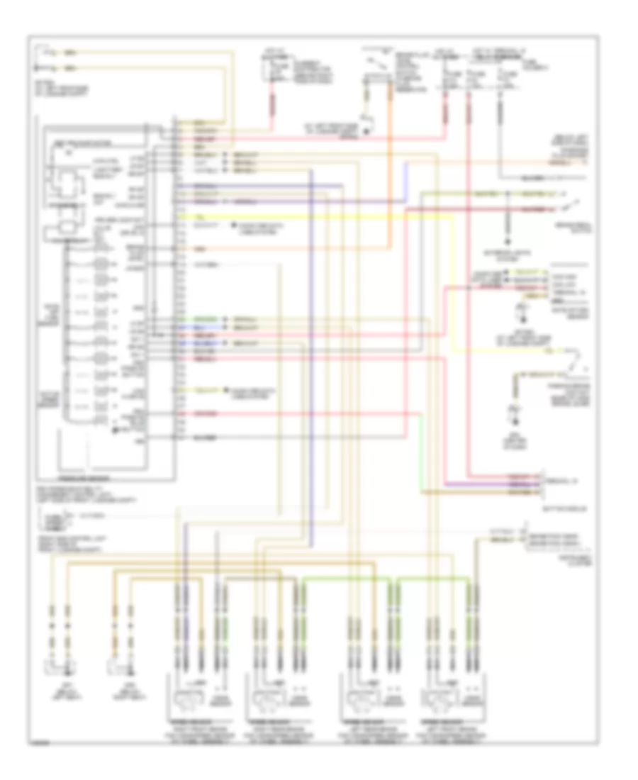
List of elements for Anti-lock Brakes Wiring Diagram for Porsche Boxster Spyder 2012:
- (at left front side of luggage compt) gp psm
- (below left side of dash)
- +bs
- Active speed sensor
- Brake fluid level
- Brake fluid level control switch (in brake fluid reservoir)
- Brake paid wear +
- Brake paid wear -
- Brake pedal switch
- Button module
- Can drive lo
- Can hi drive
- Can high
- Can low
- Computer data lines system
- Current distributor (behind right side of dash)
- Diag kline
- Diagnosis plug socket
- Eng rly act
- Engine relay
- Exterior lights system
- Front end control unit (right side of front luggage compt)
- Fuse f10 25a
- Fuse f4 10a
- Fuse f5 50a
- Fuse f8 10a
- Fuse holder c
- Gnd
- Gp psm (at left front side of luggage compt)
- Gp psm (at left frontside of luggage compt)
- Gp4 (center of dash)
- Gp6 (below right seat)
- Gp7 (below left seat)
- Hot at all times
- Hot w/ terminal 15 relay energized
- Instrument cluster
- Left front brake pad wear/speed sensor (at wheel assembly)
- Left rear brake pad wear/speed sensor (at wheel assembly)
- Lf dp
- Lf ds
- Lr dp
- Lr ds
- Lr eos
- Mtr ctrl
- Nca
- Parking brake contact (base of hand brake lever)
- Pressure sensor
- Prk brk contact
- Psm (porsche stability management control unit) (left side of front luggage compt)
- Psm passive bulb in button
- Psm passive button
- Rate off turn sensor
- Rate ofturn sensor
- Return pump motor
- Rf dp
- Right front brake pad wear/speed sensor (at wheel assembly)
- Right rear brake pad wear/speed sensor (at wheel assembly)
- Rr dp
- Rr ds
- Speed sensor
- Sw +
- Terminal 15
- U battery eng rly
- Valve relay
- Valve rly act
- Wear sensor
- Wheel
- Wheel speed a
 English