ANTI-LOCK BRAKES
Anti-lock Brakes Wiring Diagram, with ESP for Saab 9-3 Aero 2005

List of elements for Anti-lock Brakes Wiring Diagram, with ESP for Saab 9-3 Aero 2005:
- (or r1-1)
- (or r2-1)
- 15+ on and start output
- A10-2
- Abs indicator
- B16 red
- B9 red
- Brake indicator
- Brake- light switch (above brake pedal, on bracket)
- Column integration module (integral to steering column unit)
- Computer data lines system
- E65-2
- Engine bay electrical center (on left side of dash)
- Esp control module (left rear corner of engine compartment)
- Esp switch
- Fuse 5a
- Fuse 7.5a
- G15 (on left-hand structural member under battery)
- G43 (on right-hand side of knee member)
- Hot at all times
- Hs1-1
- Hs1-2(m/t) hs1-3(a/t)
- Hs2-1
- Hs2-2(m/t) hs2-3(a/t)
- Ignition switch
- Infotainment control panel
- Instrument cluster system
- Instrument panel electrical center (on left side of dash)
- Left front wheel speed sensor (on left front wheel hub)
- Left rear wheel speed sensor (on left rear wheel hub)
- Main instrument unit
- Maxi fuse 28 40a
- Maxi fuse 33 40a
- Nca
- Pnk
- R15
- R20
- R30-5
- R30-6
- R31-5
- R31-6
- Red
- Right front wheel speed sensor (on right front wheel hub)
- Right rear wheel speed sensor (on right rear wheel hub)
- Sid
- Sid control panel
- Steering angle sensor
- Traction indicator
- Trionic engine control module (right front of engine compt)
- X+ off and on output
- Yaw sensor (below gear selector assembly)
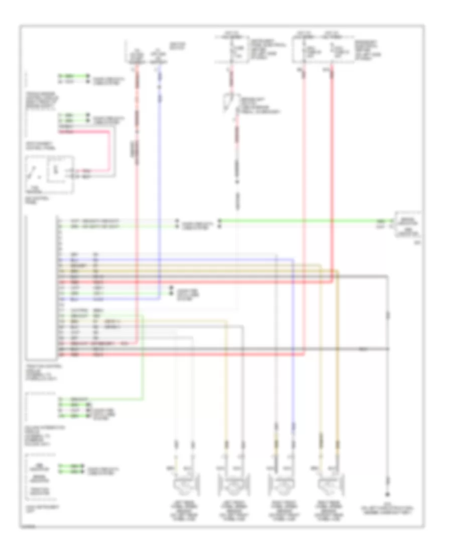
Anti-lock Brakes Wiring Diagram, without ESP for Saab 9-3 Aero 2005
List of elements for Anti-lock Brakes Wiring Diagram, without ESP for Saab 9-3 Aero 2005:
- (or r1-1)
- (or r2-1)
- 15+ on and start output
- A10-2
- Abs indicator
- B16 red
- B9 red
- Brake indicator
- Brakelight switch (above brake pedal, on bracket)
- Column integration module (integral to steering column unit)
- Computer data lines system
- E65-2
- Engine bay electrical center (on left side of dash)
- Fuse 7.5a
- G15 (on left-hand structural member under battery)
- Hot at all times
- Hs1-1
- Hs1-2(m/t) hs1-3(a/t)
- Hs2-1
- Hs2-2(m/t) hs2-3(a/t)
- Ignition switch
- Infotainment control panel
- Instrument panel electrical center (on left side of dash)
- Left front wheel speed sensor (on left front wheel hub)
- Left rear wheel speed sensor (on left rear wheel hub)
- Main instrument unit
- Maxi fuse 28 40a
- Maxi fuse 33 40a
- Nca
- Pnk
- R15
- R20
- R30-5
- R30-6
- R31-5
- R31-6
- Red
- Right front wheel speed sensor (on right front wheel hub)
- Right rear wheel speed sensor (on right rear wheel hub)
- Sid
- Sid control panel
- Tcs switch
- Traction control module (integral to hydraulic unit)
- Traction indicator
- Trionic engine control module (right front of engine compt)
- X+ off and on output