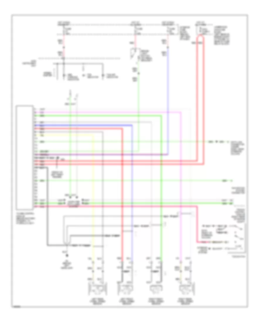
ANTI-LOCK BRAKES
Anti-lock Brakes Wiring Diagram, with Electronic Stability Program for Saab 9-5 Linear 2002

List of elements for Anti-lock Brakes Wiring Diagram, with Electronic Stability Program for Saab 9-5 Linear 2002:
- (front of left front fender)
- (left side of dash) g40
- Abs warning indicator
- Brake pressure sensor (on esp unit)
- Brake- light switch (on pedal bracket)
- Computer data lines system
- Data link connector (under dash, near steering column)
- Esp control module (behind battery, integral to hydraulic unit)
- Esp indicator
- Esp off indicator
- Esp switch
- Fuse 10a
- Fuse 15a
- Fuse 7.5a
- G2 (behind left headlamp)
- G30
- G41s (right of steering column)
- Hot at all times
- Hot in run or start
- Illum
- Interior fuse block (behind left end of dash)
- Interior lights system
- Left front wheel speed sensor
- Left rear wheel speed sensor
- Main instrument unit
- Maxi fuse 2 60a
- Navigation system connector
- Nca
- Pnk
- Red
- Right front wheel speed sensor
- Right rear wheel speed sensor
- Speed- ometer
- Steering wheel angle sensor
- Trionic control module (right rear of engine compt)
- Underhood maxi-fuse block (left rear of engine compt, attached to rear of fuse/ relay block)
- Yaw rate sensor (front of gear lever housing)
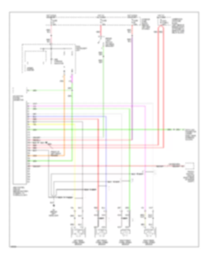
Anti-lock Brakes Wiring Diagram, with Traction Control for Saab 9-5 Linear 2002
List of elements for Anti-lock Brakes Wiring Diagram, with Traction Control for Saab 9-5 Linear 2002:
- (front of left front fender)
- Abs warning indicator
- Brake- light switch (on pedal bracket)
- Computer data lines system
- Data link connector (under dash, near steering column)
- Fuse 10a
- Fuse 15a
- Fuse 7.5a
- G2 (behind left headlamp)
- G30
- G41s (right of steering column)
- Hot at all times
- Hot in run or start
- Illum
- Interior fuse block (behind left end of dash)
- Interior lights system
- Left front wheel speed sensor
- Left rear wheel speed sensor
- Main instrument unit
- Maxi fuse 2 60a
- Navigation system connector
- Nca
- Pnk
- Red
- Right front wheel speed sensor
- Right rear wheel speed sensor
- Speed- ometer
- Tc/abs control module (behind battery, integral to hydraulic unit)
- Tcs indicator
- Tcs off indicator
- Tcs switch
- Trionic control module (right rear of engine compt)
- Underhood maxi-fuse block (left rear of engine compt, attached to rear of fuse/ relay block)
Anti-lock Brakes Wiring Diagram, without Traction Control & without Electronic Stability Program for Saab 9-5 Linear 2002
List of elements for Anti-lock Brakes Wiring Diagram, without Traction Control & without Electronic Stability Program for Saab 9-5 Linear 2002:
- (front of left front fender)
- Abs control module (behind battery, integral to hydraulic unit)
- Abs warning indicator
- Brake- light switch (on pedal bracket)
- Data link connector (under dash, near steering column)
- Fuse 10a
- Fuse 15a
- Fuse 7.5a
- G2 (behind left headlamp)
- G30
- Hot at all times
- Hot in run or start
- Interior fuse block (behind left end of dash)
- Left front wheel speed sensor
- Left rear wheel speed sensor
- Main instrument unit
- Maxi fuse 2 60a
- Navigation system connector
- Nca
- Red
- Right front wheel speed sensor
- Right rear wheel speed sensor
- Speed- ometer
- Trionic control module (right rear of engine compt)
- Underhood maxi-fuse block (left rear of engine compt, attached to rear of fuse/ relay block)