ANTI-LOCK BRAKES
Anti-lock Brakes Wiring Diagram, with Electronic Stability Program for Saab 9-5 Linear 2004

List of elements for Anti-lock Brakes Wiring Diagram, with Electronic Stability Program for Saab 9-5 Linear 2004:
- (behind left side of dash) g40
- (in engine compt, on front of left wheelwell)
- (on steering column) steering wheel angle sensor
- Abs warning indicator
- Brake pressure sensor (mounted on abs hydraulic unit)
- Brake- light switch (on pedal bracket)
- C23-1
- Computer data lines system
- Dashboard main fuse board (behind left end of dash)
- Data link connector (under dash, near steering column)
- Engine bay main fuse board (behind battery)
- Esp control module
- Esp indicator
- Esp off indicator
- Esp switch
- Fuse 10a
- Fuse 15a
- Fuse 7.5a
- G2 (behind battery)
- G30
- G41s (center of dash, behind radio)
- Hot at all times
- Hot in run or start
- Illum
- Interior lights system
- Left front wheel speed sensor (on left front wheel hub assembly)
- Left rear wheel speed sensor (on left rear wheel hub assembly)
- Main instrument unit
- Maxi fuse 2 60a
- Navigation module
- Navigation system connector
- Nca
- Pnk
- R10-1
- R11-1
- R12-1
- R13-1
- R14-1
- R15-1
- R16-1
- R17-1
- R18-1
- R19-1
- R30-2
- R30-3
- R31-4
- R31-5
- R4-1
- R56-1
- R60
- R61
- R63
- R64
- R65
- R66
- R67
- Red
- Right front wheel speed sensor (on right front wheel hub assembly)
- Right rear wheel speed sensor (on right rear wheel hub assembly)
- Speed- ometer
- Trionic control module (in right rear of engine compt)
- Yaw rate sensor (under center console, ahead of gear lever assembly)
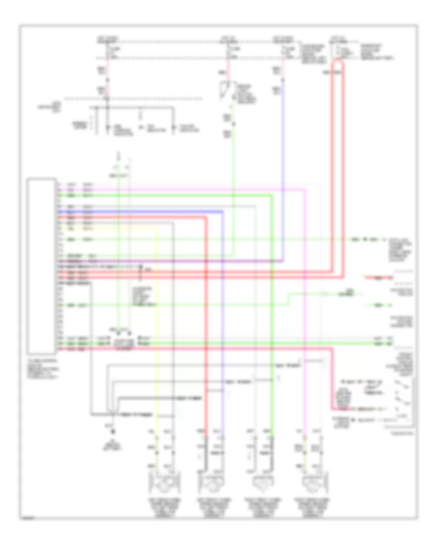
Anti-lock Brakes Wiring Diagram, with Traction Control for Saab 9-5 Linear 2004
List of elements for Anti-lock Brakes Wiring Diagram, with Traction Control for Saab 9-5 Linear 2004:
- (in engine compt, on front of left wheelwell)
- Abs warning indicator
- Brake- light switch (on pedal bracket)
- C23-1
- Computer data lines system
- Dashboard main fuse board (behind left end of dash)
- Data link connector (under dash, near steering column)
- E58-8
- E59-8
- Engine bay main fuse board (behind battery)
- Fuse 10a
- Fuse 15a
- Fuse 7.5a
- G2 (behind battery)
- G30
- G41s (center of dash, behind radio)
- Hot at all times
- Hot in run or start
- Illum
- Interior lights system
- Left front wheel speed sensor (on left front wheel hub assembly)
- Left rear wheel speed sensor (on left rear wheel hub assembly)
- Main instrument unit
- Maxi fuse 2 60a
- Navigation module
- Navigation system connector
- Nca
- Pnk
- R10-1
- R11-1
- R12-1
- R13-1
- R14-1
- R15-1
- R16-1
- R17-1
- R18-1
- R19-1
- R30-2
- R30-3
- R31-4
- R31-5
- R4-1
- R56
- Red
- Right front wheel speed sensor (on right front wheel hub assembly)
- Right rear wheel speed sensor (on right rear wheel hub assembly)
- Speedo- meter
- Tc-abs control module (behind battery, integral to hydraulic unit)
- Tcs indicator
- Tcs off indicator
- Tcs switch
- Trionic control module (in right rear of engine compt)