ANTI-LOCK BRAKES
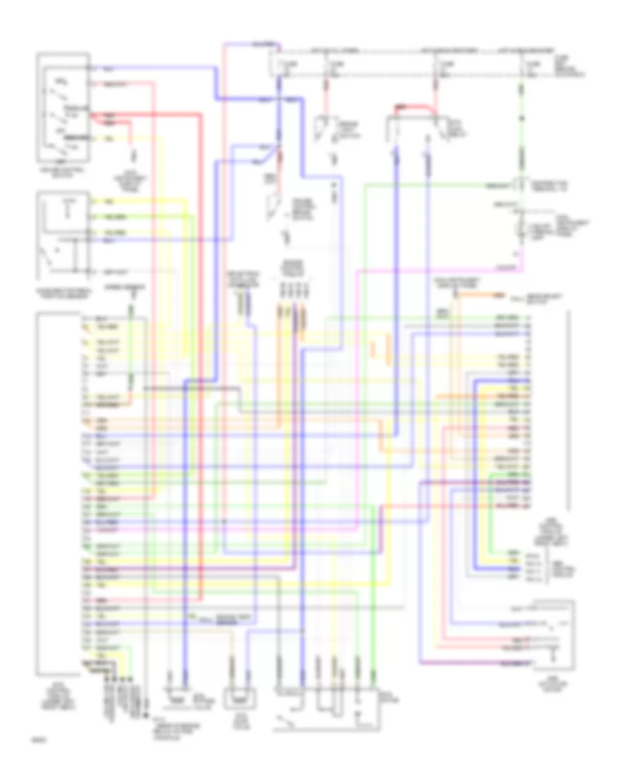
Anti-lock Brake Wiring Diagrams, with Traction Control, Automatic Mark IV (1 of 2) for Saab 9000 CSE 1994

List of elements for Anti-lock Brake Wiring Diagrams, with Traction Control, Automatic Mark IV (1 of 2) for Saab 9000 CSE 1994:
- (left rear side of engine compartment,
- 721a
- 723a
- 725a
- 727a
- 960b
- Abs control module
- Abs diode
- Abs fuse box (behind brake fluid reservoir)
- Abs main relay
- Abs pump relay
- Abs valve block
- Anti lock indicator
- App sensor
- Asr control module
- Brake light switch
- Edu data link connector
- Fuse 1 30a
- Fuse 15a
- Fuse 2 30a
- Fuse 3 10a
- Fuse box (behind glove box)
- G104 (left structural member)
- Hot at all times
- Hot in run
- Hot in run, bulb test or start (from ignition switch)
- Hydraulic pump motor
- Left front in
- Left front out
- Left front wheel sensor
- Left rear in
- Left rear out
- Left rear wheel sensor
- Main instrument display panel
- Nca
- On battery tray)
- Pin 10
- Pin 21
- Pin 8
- Pin 9
- Red
- Right front in
- Right front out
- Right front wheel sensor
- Right rear in
- Right rear out
- Right rear wheel sensor
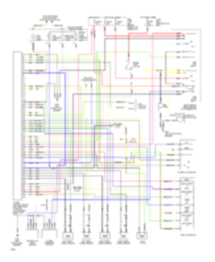
Anti-lock Brake Wiring Diagrams, with Traction Control, Automatic Mark IV (2 of 2) for Saab 9000 CSE 1994
List of elements for Anti-lock Brake Wiring Diagrams, with Traction Control, Automatic Mark IV (2 of 2) for Saab 9000 CSE 1994:
- (rear of engine,
- Abs control module
- Accelerator pedal position sensor
- Asr actuator motor
- Asr control module (under left front seat)
- Below intake manifold)
- Brake light switch
- Cooling fan relay
- Cruise control brake switch
- Cruise control switch
- Distribution terminal +15
- Drive-train data link connector
- Engine control module
- Engine temp. sensor
- Ets bypass valve
- Ets control module (under left front seat)
- Ets dump valve
- Ets main relay
- Ets motor
- Fuse 10a
- Fuse 15a
- Fuse 25a
- Fuse 5a
- Fuse box (behind glove box)
- G114
- Gear select pin 4 switch
- Hot at all times
- Hot in run or start
- Main instrument display panel
- Main instrument display panel pin 4
- Off
- Pin 10
- Pin 11
- Pin 12
- Pin 2
- Pin 27
- Pin 35
- Pin 57
- Pin 58
- Pin 6
- Pin 9
- Pressure sw cooling fan
- Red
- Resume
- Set
- Speed sensor
- Tcs off warning lamp
- Therm0stat anti-freeze
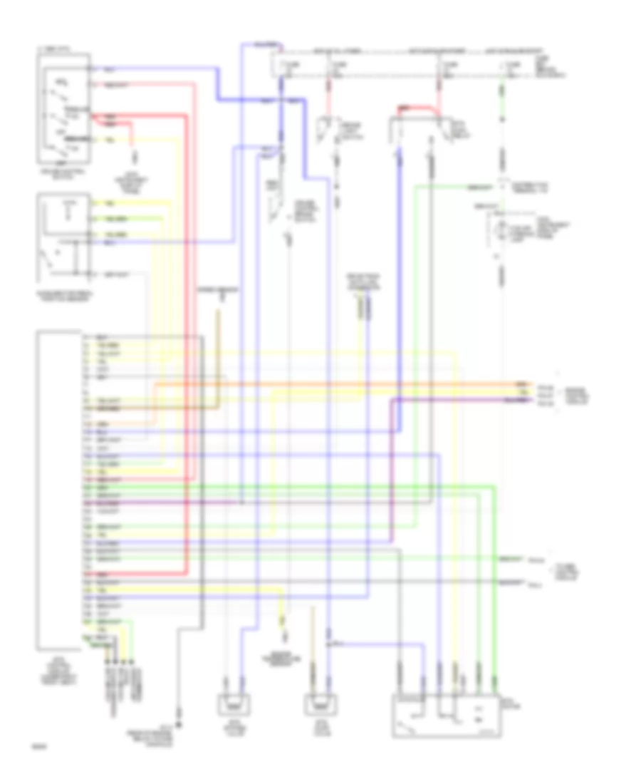
Anti-lock Brake Wiring Diagrams, with Traction Control, Manual Mark II (1 of 2) for Saab 9000 CSE 1994
List of elements for Anti-lock Brake Wiring Diagrams, with Traction Control, Manual Mark II (1 of 2) for Saab 9000 CSE 1994:
- 720b
- 721a
- 723a
- 725a
- 727a
- 750a
- 960b
- Abs diode
- Abs fuse box (behind brake fluid reservoir)
- Abs main relay
- Abs pump relay
- Abs valve block
- Abs/tcs warning lamp
- Brake fluid level sensor
- Brake fluid level warning lamp
- Brake light switch
- Edu data link connector
- Ets control module
- Fuse 1 30a
- Fuse 15a
- Fuse 2 30a
- Fuse 3 10a
- Fuse box (behind glove box)
- G104 (left structural member)
- Hot at all times
- Hot in run
- Hot in run, bulb test or start (from ignition switch)
- Hydraulic pump motor
- Left front in
- Left front out
- Left front wheel sensor
- Left rear wheel sensor
- Main instrument display panel
- Main valve
- Nca
- Pin 29
- Pin 32
- Rear in
- Rear out
- Red
- Right front in
- Right front out
- Right front wheel sensor
- Right rear wheel sensor
- Tc-abs control module (left rear side of engine compartment, on battery tray)
- Tc-abs pressure switch
- Tc-abs valve block
- Tcs indic. lamp
- Tcs warning lamp
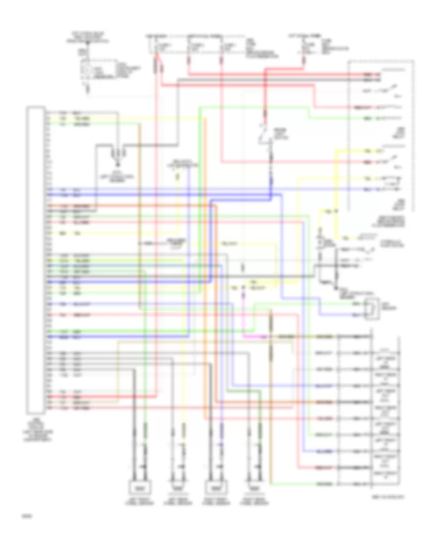
Anti-lock Brake Wiring Diagrams, with Traction Control, Manual Mark II (2 of 2) for Saab 9000 CSE 1994
List of elements for Anti-lock Brake Wiring Diagrams, with Traction Control, Manual Mark II (2 of 2) for Saab 9000 CSE 1994:
- Accelerator pedal position sensor
- Anti-freeze thermostat
- Brake light switch
- C 1995 vftc
- Cruise control brake switch
- Cruise control switch
- Distribution terminal +15
- Drive-train data link connector
- Engine control module
- Engine temperature sensor
- Ets bypass valve
- Ets control module (under right front seat)
- Ets dump valve
- Ets main relay
- Ets motor
- Fuse 10a
- Fuse 15a
- Fuse 25a
- Fuse 5a
- Fuse box (behind glove box)
- G114 (rear of engine, below intake manifold)
- Hot at all times
- Hot in run or start
- Main instrument display panel
- Off
- Pin 24
- Pin 35
- Pin 4
- Pin 57
- Pin 58
- Pin 6
- Pressure switch cooling fan
- Red
- Relay cooling fan
- Resume
- Set
- Speed sensor pin 2
- Tc-abs control module
- Tcs off warning lamp
Anti-lock Brake Wiring Diagrams, without Traction Control, Mark IV for Saab 9000 CSE 1994
List of elements for Anti-lock Brake Wiring Diagrams, without Traction Control, Mark IV for Saab 9000 CSE 1994:
- (left rear side of engine compartment)
- 721a
- 723a
- 725a
- 727a
- 960b
- Abs control module
- Abs diode
- Abs fuse box (behind brake fluid reservoir)
- Abs main relay
- Abs pump relay
- Abs valve block
- Anti lock indicator
- App sensor
- Brake light switch
- Edu data link connector
- Fuse 1 30a
- Fuse 15a
- Fuse 2 30a
- Fuse 3 10a
- Fuse box (behind glove box)
- G104 (left structural member)
- Hot at all times
- Hot in run
- Hot in run, bulb test or start (from ignition switch)
- Hydraulic pump motor
- Left front in
- Left front out
- Left front wheel sensor
- Left rear in
- Left rear out
- Left rear wheel sensor
- Main instrument display panel
- Nca
- Red
- Right front in
- Right front out
- Right front wheel sensor
- Right rear in
- Right rear out
- Right rear wheel sensor