ANTI-LOCK BRAKES
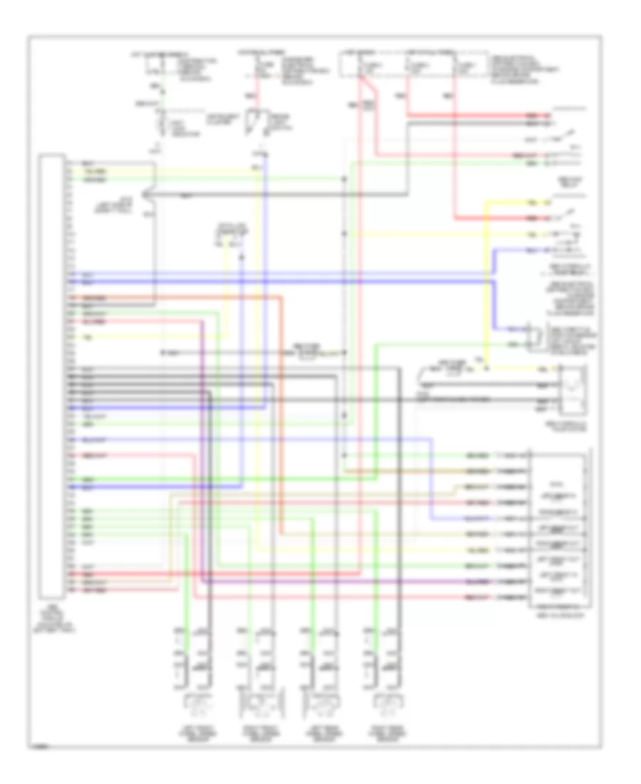
Anti-lock Brake Wiring Diagrams for Saab 9000 CSE 1998
List of elements for Anti-lock Brake Wiring Diagrams for Saab 9000 CSE 1998:
- (mounted on battery tray)
- +15
- Abs control module
- Abs diode
- Abs electrical distribution box (in engine compartment, behind brake fluid reservoir)
- Abs hydraulic pump motor
- Abs hydraulic pump relay
- Abs main relay
- Abs throttle position sensor (on vacuum servo, mounted on bulkhead)
- Abs valve block
- Anti lock indicator
- Brake light switch
- Dashboard electrical distribution box (behind glove box)
- Data link connector
- Distribution terminal (behind glove box)
- Fuse 1 30a
- Fuse 15a
- Fuse 2 30a
- Fuse 3 10a
- G102 (left front shock tower)
- G116 (left side of safety wall)
- Hot at all times
- Hot in run
- Hot in start or run
- Instrument cluster
- Left front in
- Left front out
- Left front wheel speed sensor
- Left rear in
- Left rear out
- Left rear wheel speed sensor
- Nca
- Red
- Right front in
- Right front out
- Right front wheel speed sensor
- Right rear in
- Right rear out
- Right rear wheel speed sensor
 Deutsch