ANTI-LOCK BRAKES
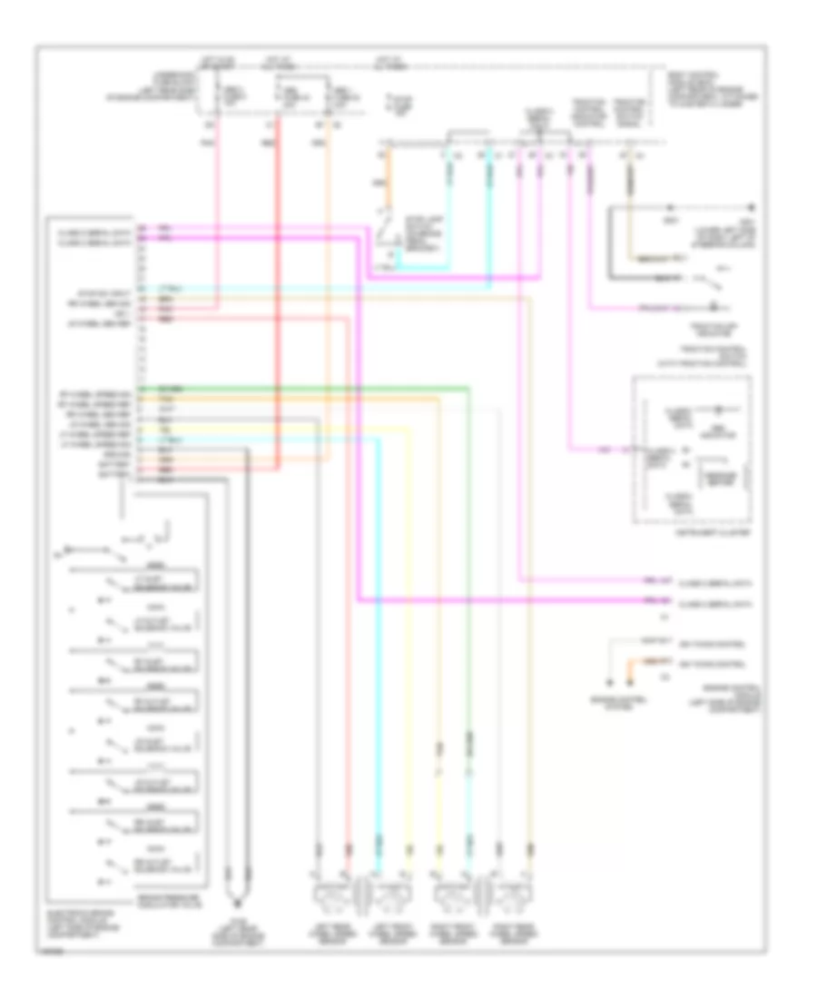
Anti-lock Brakes Wiring Diagram for Saturn Ion 3 2003
List of elements for Anti-lock Brakes Wiring Diagram for Saturn Ion 3 2003:
- Abs 1 fuse 22 20a
- Abs 2 fuse 8 10a
- Abs fuse 40 40a
- Abs indicator
- Battery
- Body control module (bcm) (left rear of engine compartment, attached to master cylinder)
- Brake pressure modulator valve
- Class 2 serial data
- Electronic brake control module (left side of engine compartment)
- Engine control module (left side of engine compartment)
- Engine control system
- G109 (left rear side of engine compartment)
- G201 (lower left side of dash, left of steering column)
- Ground
- Hot at all times
- Hot in on or start
- Ign 1
- Ign timing control
- Instrument cluster
- Left front wheel speed sensor
- Left rear wheel speed sensor
- Lf inlet solenoid valve
- Lf outlet solenoid valve
- Lf wheel speed ref
- Lf wheel speed sig
- Lr inlet solenoid valve
- Lr outlet solenoid valve
- Lr wheel sen ref
- Lr wheel sen sig
- Message center
- Pnk
- Red
- Rf inlet solenoid valve
- Rf outlet solenoid valve
- Rf wheel speed ref
- Rf wheel speed sig
- Right front wheel speed sensor
- Right rear wheel speed sensor
- Rr inlet solenoid valve
- Rr outlet solenoid valve
- Rr wheel sen ref
- Rr wheel sen sig
- S221
- Stop fuse 15a
- Stop lamp switch (on brake pedal bracket)
- Stop sw input
- Tan
- Traction control indicator control
- Traction control switch (with traction control)
- Traction control switch signal
- Traction off indicator
- Underhood fuse block (left rear side of engine compartment)
 English