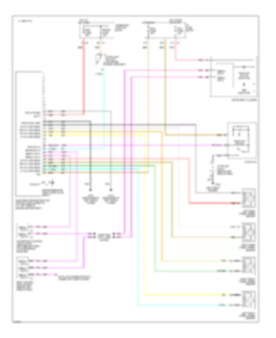
ANTI-LOCK BRAKES
Anti-lock Brake Wiring Diagrams for Saturn SL 2000
List of elements for Anti-lock Brake Wiring Diagrams for Saturn SL 2000:
- (left front fender)
- A c6
- A11 c1
- Abs fuse 50a
- Abs indicator
- Batt
- Bo7
- Bo8
- Bo9
- Body control module (bcm) (behind left side of dash)
- Brake fuse 15a
- Brake pressure modulator valve (bpmv)
- Brake sw in
- C 1995 vftc
- Computer data lines system
- Data link connector (dlc) (under left side of dash)
- E10
- E2 c1
- Electronic brake/traction control module (ebtcm) (at left rear of engine compartment)
- F10
- G100
- G102 (near base of left shock tower)
- Hot at all times
- Hot in run
- Hot in run or start
- I/p fuse block
- I/p splice pack 1 (behind left side of dash)
- I/p switch
- Ign
- Ign 1 fuse 10a
- Ign 3 fuse 15a
- Instrument cluster
- Left front wheel speed sensor
- Left rear wheel speed sensor
- Lf whl spd sens
- Lr whl spd sens
- Module sol grd
- Nca
- Pmp mtr grd
- Pnk
- Powertrain control module (pcm) (between battery & power brake booster)
- Pwr out
- Red
- Rf whl spd sens
- Right front wheel speed sensor
- Right rear wheel speed sensor
- Rr whl spd sens
- Serial data
- Stoplight switch (on brake pedal bracket)
- Tan
- Trac sw in
- Traction active indicator
- Traction off ind
- Underhood junction block
 English