ANTI-LOCK BRAKES
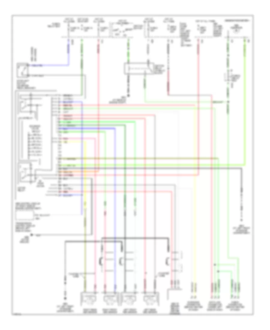
Anti-lock Brakes Wiring Diagram, without Traction Control for Subaru Baja 2003
List of elements for Anti-lock Brakes Wiring Diagram, without Traction Control for Subaru Baja 2003:
- (w/o cruise)
- Abs "g" sensor (below center console)
- Abs control module (at right side of engine compartment)
- Abs indicator
- Abs motor ground
- Acc
- B152
- B158
- B54
- Check connector (behind center of dash)
- Combination meter
- Data link connector (under left side of dash)
- Diagnosis connector (behind center of dash)
- F34
- F37
- F41
- F68
- Fl in
- Fl out
- Fr in
- Fr out
- Fuse & relay box
- Fuse 16 20a
- Fuse 18 15a
- Fuse 5 15a
- Fuse 8 30a
- Gb-2 (at left front of engine compartment)
- Gb-3 (at rear of engine compt)
- Hot at all times
- Hot in on or start
- I10
- I12
- Ignition relay (in relay block)
- Ignition switch
- Left front abs sensor
- Left rear abs sensor
- Main fuse box (at left side of engine compt, at rear of battery)
- Motor relay
- Nca
- Off
- Pnk
- Pump motor
- Red
- Right front abs sensor
- Right rear abs sensor
- Rl in
- Rl out
- Rr in
- Rr out
- Sbf holder (at left side of engine compt)
- Sbf-5 fuse 30a
- Sbf-7 fuse 30a
- Solenoid valve
- Start
- Stoplight switch (on brake pedal bracket)
- Transmission control module (behind left side of dash)
- Twisted wire
- Valve relay
 English