ANTI-LOCK BRAKES
Anti-lock Brakes Wiring Diagram for Subaru Forester XS 2004
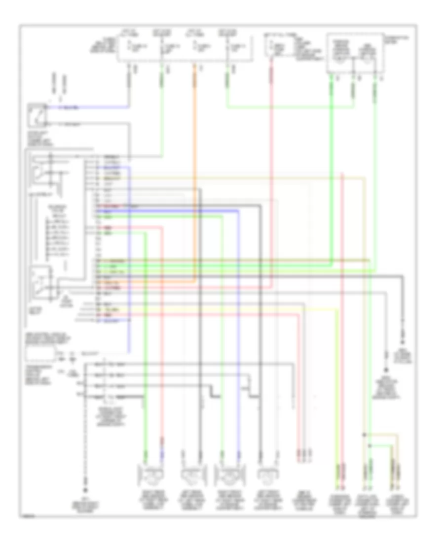
List of elements for Anti-lock Brakes Wiring Diagram for Subaru Forester XS 2004:
- 2.5l
- 2.5l turbo
- Abs "g" sensor (under rear of center console)
- Abs control module (on right front side of engine compartment)
- Abs warning light ind
- B158
- B271
- B302 (abs motor ground) (at front center of engine compt)
- B54
- Check connector (under left side of dash)
- Combination meter
- Data link connector (under dash, left of steering column)
- Diagnosis connector (under left side of dash)
- F41
- Fl in
- Fl out
- Fr in
- Fr out
- Fuse & relay box (behind left side of dash)
- Fuse 14 10a
- Fuse 16 20a
- Fuse 18 15a
- Fuse 8 30a
- Gb-2 (at base of right "a" pillar)
- Gf-1 (behind right side of front bumper)
- Hot at all times
- Hot in on or start
- I10
- I11
- I12
- Left front abs sensor (at right rear of engine compartment)
- Left rear abs sensor (at left rear wheel hub assembly)
- Motor relay
- Nca
- Parking brake warning light ind
- Pump motor
- Red
- Right front abs sensor (at right rear of engine compartment)
- Right rear abs sensor (at right rear wheel hub assembly)
- Rl in
- Rl out
- Rr in
- Rr out
- Sbf holder (abs) (on left side of engine compartment)
- Sbf-8 fuse 30a
- Shield joint connector (at right front corner of engine compt)
- Solenoid valve
- Stoplight switch (under left side of dash)
- Transmission control module (behind left side of dash)
- Valve relay
- W/ cruise
- W/o cruise
 English